High pressure manifold, assembly, system and method

a technology of high pressure manifolds and manifolds, applied in fluid pressure control, instruments, borehole/well accessories, etc., can solve the problems of equipment congestion, waste of manifold costs, and ineffective reduction of equipment congestion, so as to reduce equipment congestion

Active Publication Date: 2018-10-25
MGB OILFIELD SOLUTIONS LLC
View PDF16 Cites 128 Cited by
  • Summary
  • Abstract
  • Description
  • Claims
  • Application Information

AI Technical Summary

Problems solved by technology

In such instances, only part of the manifold is actually in use meaning that there is a wasted expense associated with the cost of using a ten or twelve station manifold.
Also, because of the complexity of construction of such manifolds, if a particular section of the manifold needs repair or inspection the entire manifold unit is typically removed and repaired off site requiring a different replacement manifold to be inserted into operation.
However, this type of manifold makes use of an outlay of frac pumps different than the two opposing rows of frac pumps described above and are not necessarily effective for reducing the congestion of equipment at a well site.

Method used


Image

  • High pressure manifold, assembly, system and method
  • High pressure manifold, assembly, system and method
  • High pressure manifold, assembly, system and method

Examples


example 1

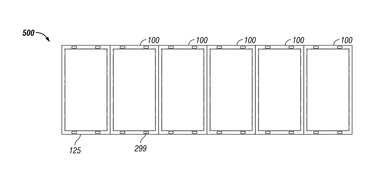
[0112]In a first non-limiting example, a manifold system 500 as shown in FIG. 37 is provided for use with a right hand pump bank having four hydraulic fracturing pumps and a left hand pump bank having four hydraulic fracturing pumps. In this embodiment, a total of two four pump count (or two “four frac pump station”) manifold sub-assemblies 100 are assembled to provide a manifold system 500 for operation with a total of eight hydraulic fracturing pumps at a well site.

example 2

[0113]In a second non-limiting example, a manifold system 500 as shown in FIG. 38 is provided for use with a right hand pump bank having four hydraulic fracturing pumps and a left hand pump bank having four hydraulic fracturing pumps. In this embodiment, one six pump count (“six frac pump station”) manifold sub-assembly 100 is assembled with one two pump count (“two frac pump station”) manifold sub-assembly 100 to provide a manifold system 500 for operation with a total of eight hydraulic fracturing pumps at a well site.

example 3

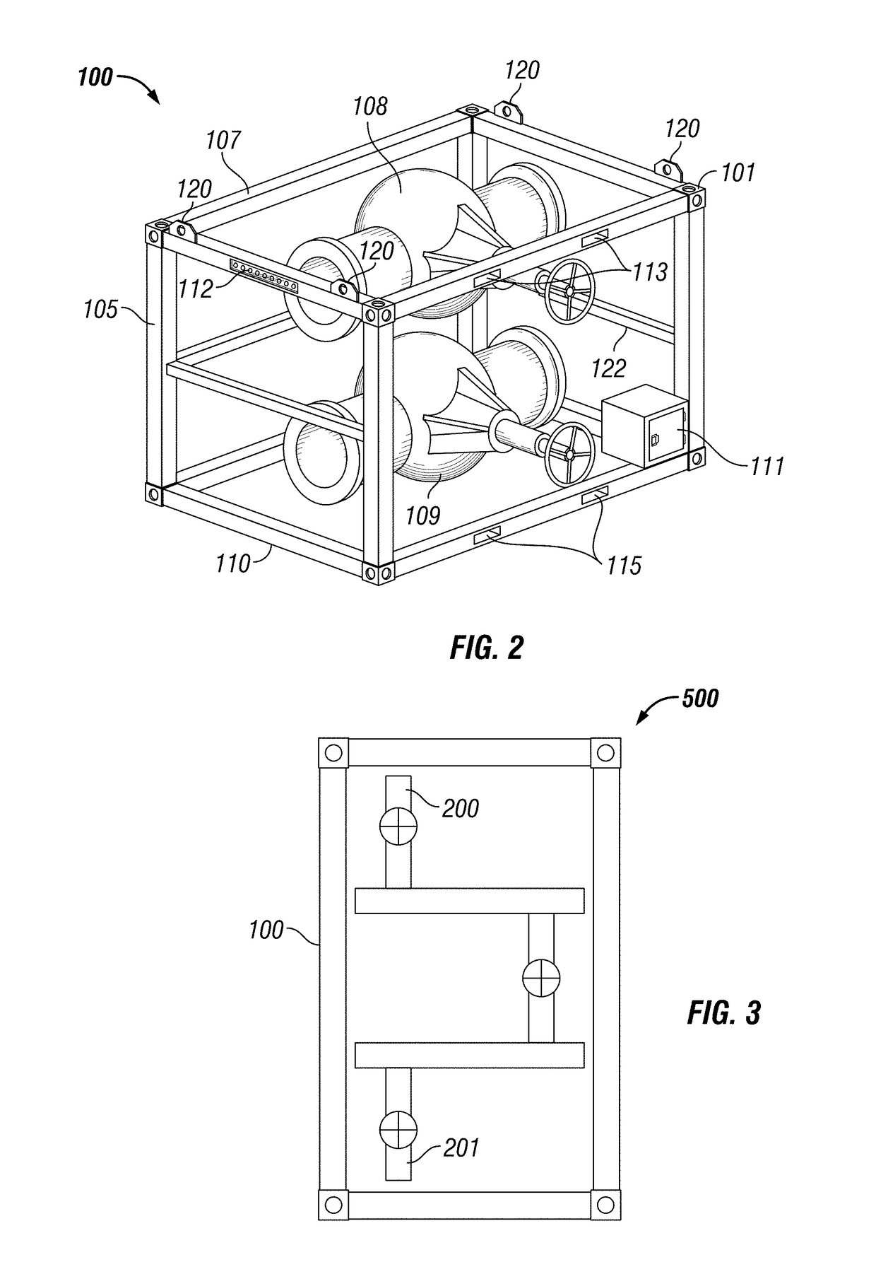
[0114]In a third non-limiting example, a four pump count manifold sub-assembly 100 as shown in FIG. 39 is provided. The manifold sub-assembly 100 may be secured to a framework 105 or the manifold sub-assembly 100 may be mounted to a chassis.


PUM


Abstract

The present application is directed to a manifold system for low pressure and high pressure fluids. The manifold system may include one or more manifold sub-assemblies that may be assembled together, separated apart and replaced as desired. In oil and gas hydraulic fracturing operations, each manifold sub-assembly includes two or more low pressure fluid lines and two or more high pressure fluid lines for fluidly communicating with hydraulic fracturing pumps. High pressure fluid may exit the manifold system via a single line or multiple lines.

Description

CROSS-REFERENCE TO RELATED APPLICATIONS[0001]This application claims benefit of U.S. Provisional Patent Application Ser. No. 62 / 489,468, filed on Apr. 25, 2017, the content of which is hereby incorporated by reference in its entirety. This application also claims benefit of U.S. Provisional Patent Application Ser. No. 62 / 505,066, filed on May 11, 2017, the content of which is hereby incorporated by reference in its entirety. This application also claims benefit of U.S. Provisional Patent Application Ser. No. 62 / 617,164, filed on Jan. 12, 2018, the content of which is hereby incorporated by reference in its entirety.STATEMENT REGARDING FEDERALLY SPONSORED RESEARCH OR DEVELOPMENT[0002]Not applicable.BACKGROUND OF THE APPLICATION[0003]The application relates generally to a low fluid pressure and high fluid pressure manifold system operable in oil and gas production.[0004]Hydraulic fracturing, sometimes called “fracing” or “fracking” is a process for increasing the flow of oil or gas fr...

Claims


Application Information

Patent Timeline
Patent Type & Authority Applications(United States)
IPC IPC(8): G05D7/06E21B43/26G05D16/20
CPCG05D7/0664E21B43/26G05D16/206G05D16/2073G05D16/04G05D7/01E21B43/2607
Inventor BISHOP, MARK DANIEL
Owner MGB OILFIELD SOLUTIONS LLC
Why Eureka
Try Eureka