Real-time camera position estimation with drift mitigation in incremental structure from motion

Active Publication Date: 2018-11-01
LOCKHEED MARTIN CORP
View PDF0 Cites 29 Cited by
  • Summary
  • Abstract
  • Description
  • Claims
  • Application Information

AI Technical Summary

Problems solved by technology

However, GPUs such as those provided by NVIDIA are not PLCs, but rather a sort of specialized general purpose computer.

Method used


Image

  • Real-time camera position estimation with drift mitigation in incremental structure from motion
  • Real-time camera position estimation with drift mitigation in incremental structure from motion
  • Real-time camera position estimation with drift mitigation in incremental structure from motion

Examples


Embodiment Construction

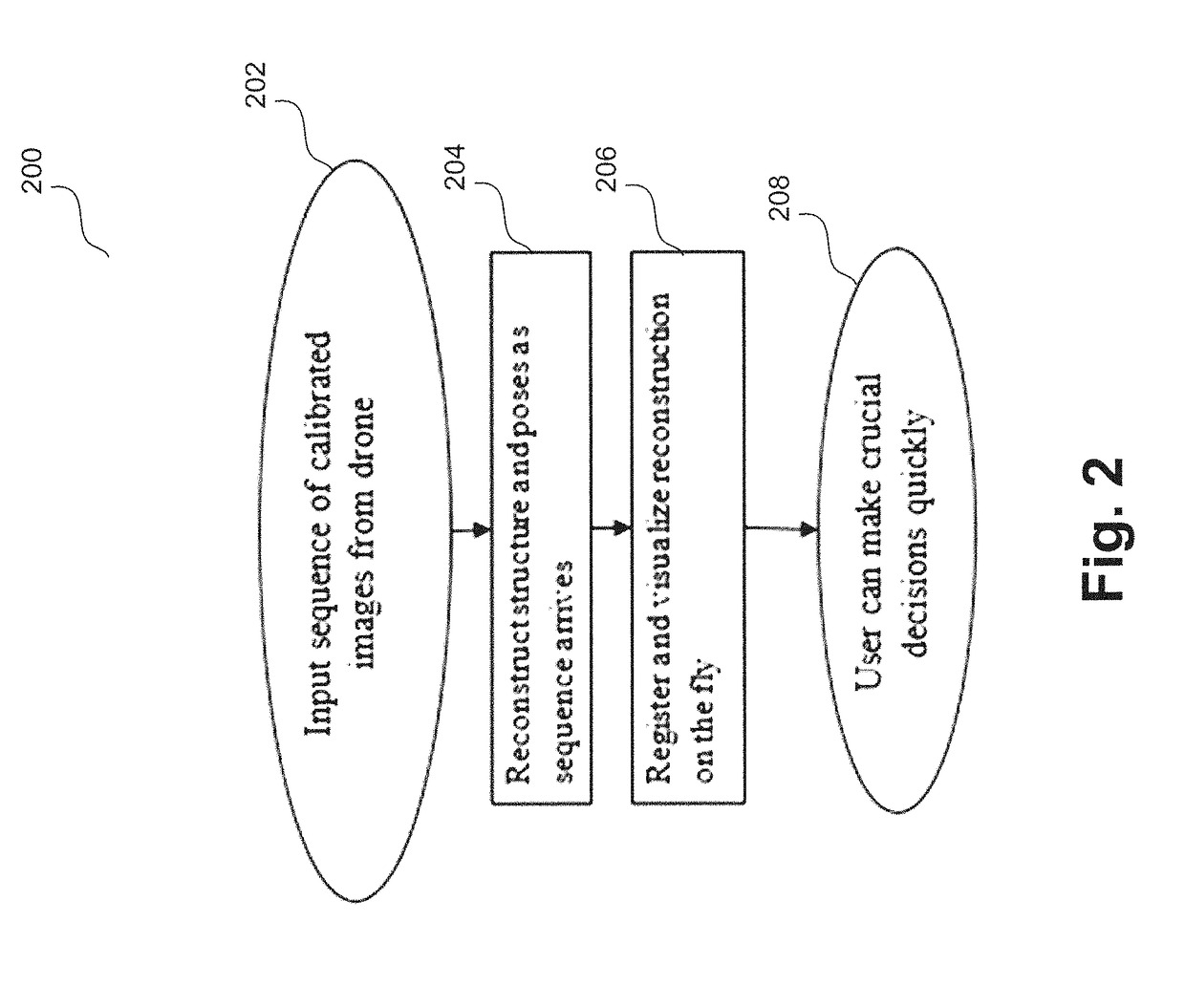
[0025]Embodiments generate a 3D reconstruction as a textured model, in real or near-real time as the imagery is obtained, and place that model in a 3D visualization of the earth from live imagery (e.g., still images or video) from a manned or unmanned vehicle. Accordingly, embodiments allow for fast decision making by providing rapid feedback for inspection (e.g., in commercial applications), reconnaissance (i.e., military observation of a region to locate an enemy or ascertain strategic features), disaster relief, or other time-sensitive operations.

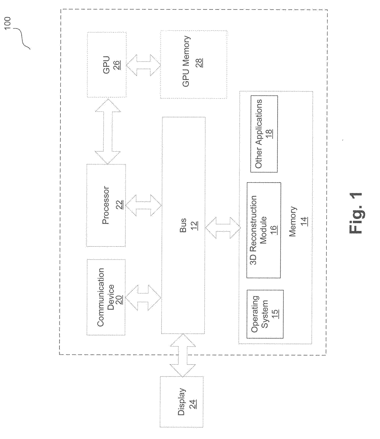
[0026]FIG. 1 illustrates a block diagram of a system 100 in accordance with one embodiment of the invention. In some embodiments, system 100 may function as a 3D reconstruction system as disclosed below. In these embodiments, system 100 may not include one or more of the modules depicted in FIG. 1, such as a display 24.

[0027]Although shown as a single system, the functionality of system 100 can be implemented as a distributed system. Sys...


PUM


Abstract

A system provides camera position and point cloud estimation 3D reconstruction. The system receives images and attempts existing structure integration to integrate the images into an existing reconstruction under a sequential image reception assumption. If existing structure integration fails, the system attempts dictionary overlap detection by accessing a dictionary database and searching to find a closest matching frame in the existing reconstruction. If overlaps are found, the system matches the images with the overlaps to determine a highest probability frame from the overlaps, and attempts existing structure integration again. If overlaps are not found or existing structure integration fails again, the system attempts bootstrapping based on the images. If any of existing structure integration, dictionary overlap detection, or bootstrapping succeeds, and if multiple disparate tracks have come to exist, the system attempts reconstructed track merging.

Description

FIELD[0001]One embodiment is directed generally to image reconstruction, and in particular, to real-time three-dimensional (“3D”) reconstruction.BACKGROUND INFORMATION[0002]The advent of high-performance processors has led to systems that can perform 3D reconstruction of images. Generally, 3D reconstruction from multiple images refers to the creation of 3D models from a set of images, and is the reverse process of obtaining two-dimensional (“2D”) images from 3D scenes. Some 3D reconstruction systems incorporate texture mapping which refers to a method for defining high frequency detail surface texture or color information on a computer generated graphic or 3D model. A textured model is a computer generated graphic or 3D model obtained by texture mapping. Some 3D reconstruction systems provide a level-of-detail texture model. Level-of-detail refers to decreasing the complexity of a 3D model representation as it moves away from the viewer or according to other metrics such as object i...

Claims


Application Information

Patent Timeline
Patent Type & Authority Applications(United States)
IPC IPC(8): G06T11/00G06K9/62G06T7/73G06F17/30G06V20/13G06V20/17
CPCG06T11/005G06K9/6201G06T7/74G06F17/30256G06F17/30268G06F17/3028G06T17/20G06T2207/30244G06T2215/16G06T2210/52G06T15/005G06T15/205G06T2207/10028G06T2207/10016G06T7/579G06V20/64G06V20/13G06V30/242G06V10/757G06V20/17G06F16/51G06F16/5838G06F16/5866G06F18/22G06F16/5862
Inventor JONES, MICHAELDICKIN, ADAM JAMES
Owner LOCKHEED MARTIN CORP
Why Eureka
Try Eureka