

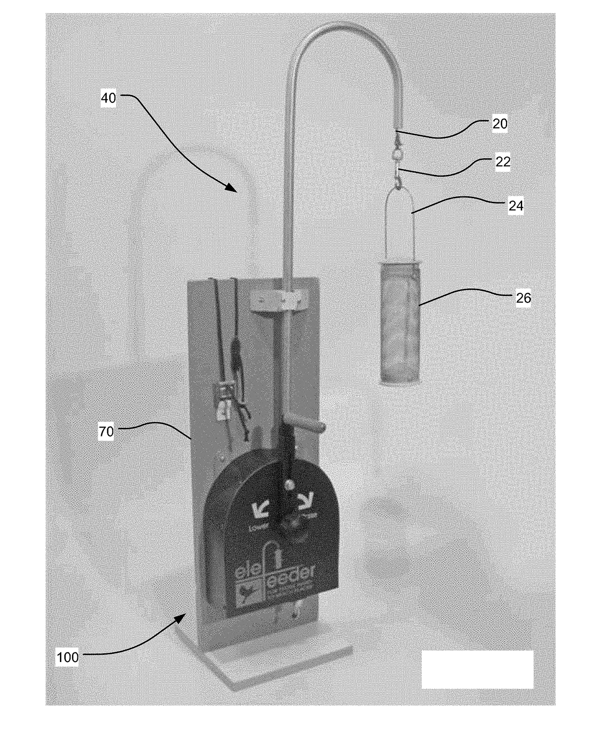
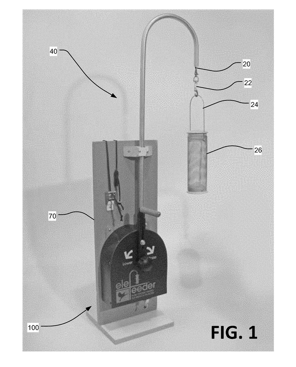
Rotary High Lifter and Controlled Descender
a high-lifting, controlled technology, applied in the direction of gearing, mechanical control devices, instruments, etc., can solve the problems of difficult to keep certain types of non-bird species away from feeders, difficult to access such feeders (to clean, refill, etc., and achieve the effect of increasing friction against the ratchet spool
- Summary
- Abstract
- Description
- Claims
- Application Information
AI Technical Summary
Benefits of technology
Problems solved by technology
Method used
Image

Examples
Embodiment Construction
[0030]In the following discussion, numerous specific details are set forth to provide a thorough understanding of the present disclosure. However, those skilled in the art will appreciate that embodiments may be practiced without such specific details. Furthermore, lists and / or examples are often provided and should be interpreted as exemplary only and in no way limiting embodiments to only those examples. Similarly, in this disclosure, language such as “could, should, may, might, must, have to, can, would, need to, is, is not”, etc. and all such similar language shall be considered interchangeable whenever possible such that the scope of the invention is not unduly limited. For example, a comment such as: “item X is used” can be interpreted to read “item X can be used”.
[0031]Exemplary embodiments are described below and in the accompanying Figures. The following detailed description provides a review of the drawing Figures in order to provide a thorough understanding of, and an ena...
PUM
 Abstract
Description
Claims
Application Information