System and method for determining the current condition of power contacts

a technology of current condition and power contacts, applied in the direction of coupling contact members, coupling device connections, instruments, etc., can solve the problems of increasing the cost of down time and speeding up contact wear

Active Publication Date: 2018-11-08
SCHNEIDER ELECTRIC USA INC
View PDF0 Cites 6 Cited by
  • Summary
  • Abstract
  • Description
  • Claims
  • Application Information

AI Technical Summary

Problems solved by technology

As the power contacts 18 and 22 wear, the gap between them increases and their surfaces become more irregular forming more arcing points, which speed up contact wear.
Since so much down time is consumed doing the periodic inspection the power contacts 14 are usually replaced regardless of their wear condition, which adds to the down time cost.

Method used


Image

  • System and method for determining the current condition of power contacts
  • System and method for determining the current condition of power contacts
  • System and method for determining the current condition of power contacts

Examples


Embodiment Construction

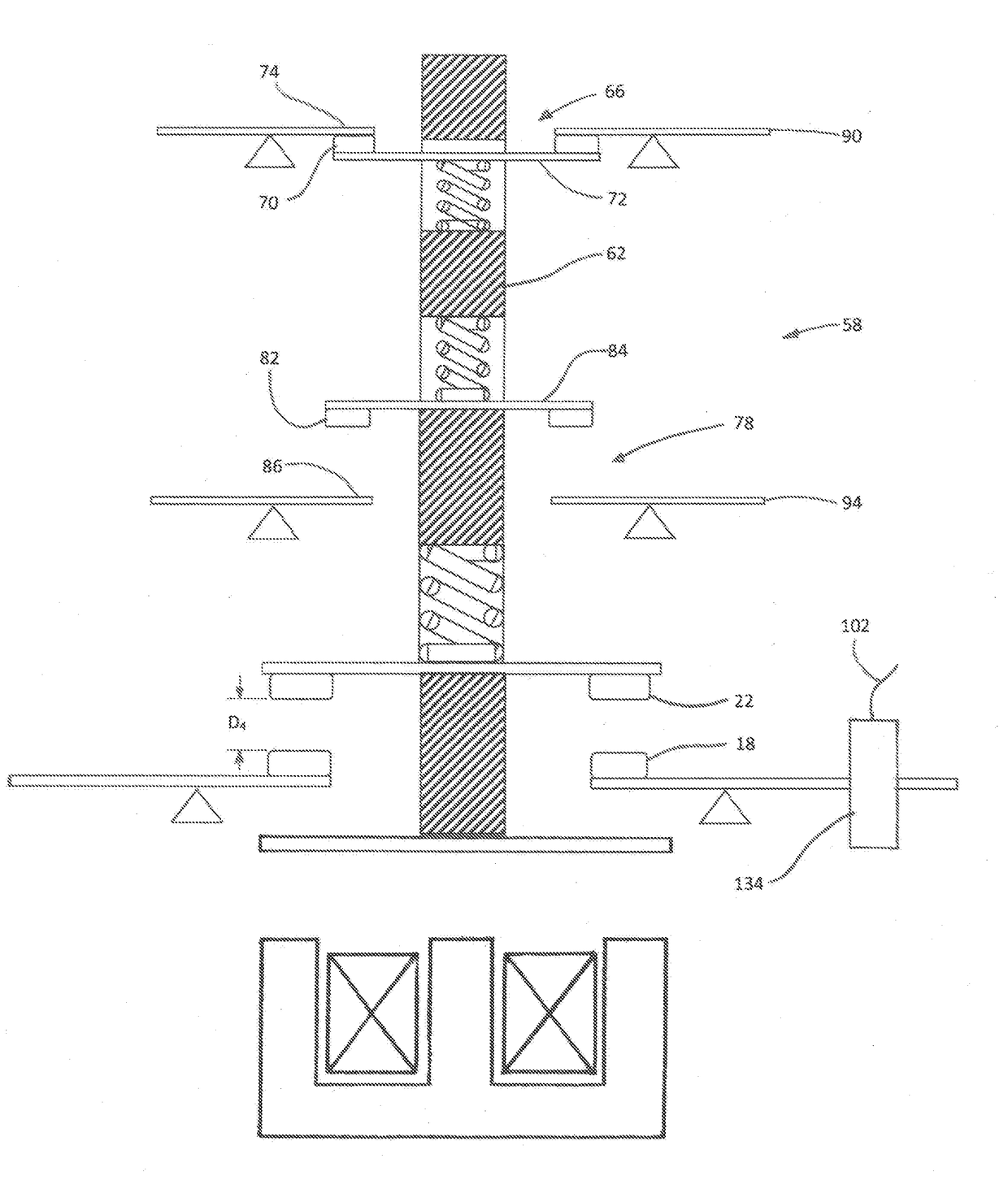
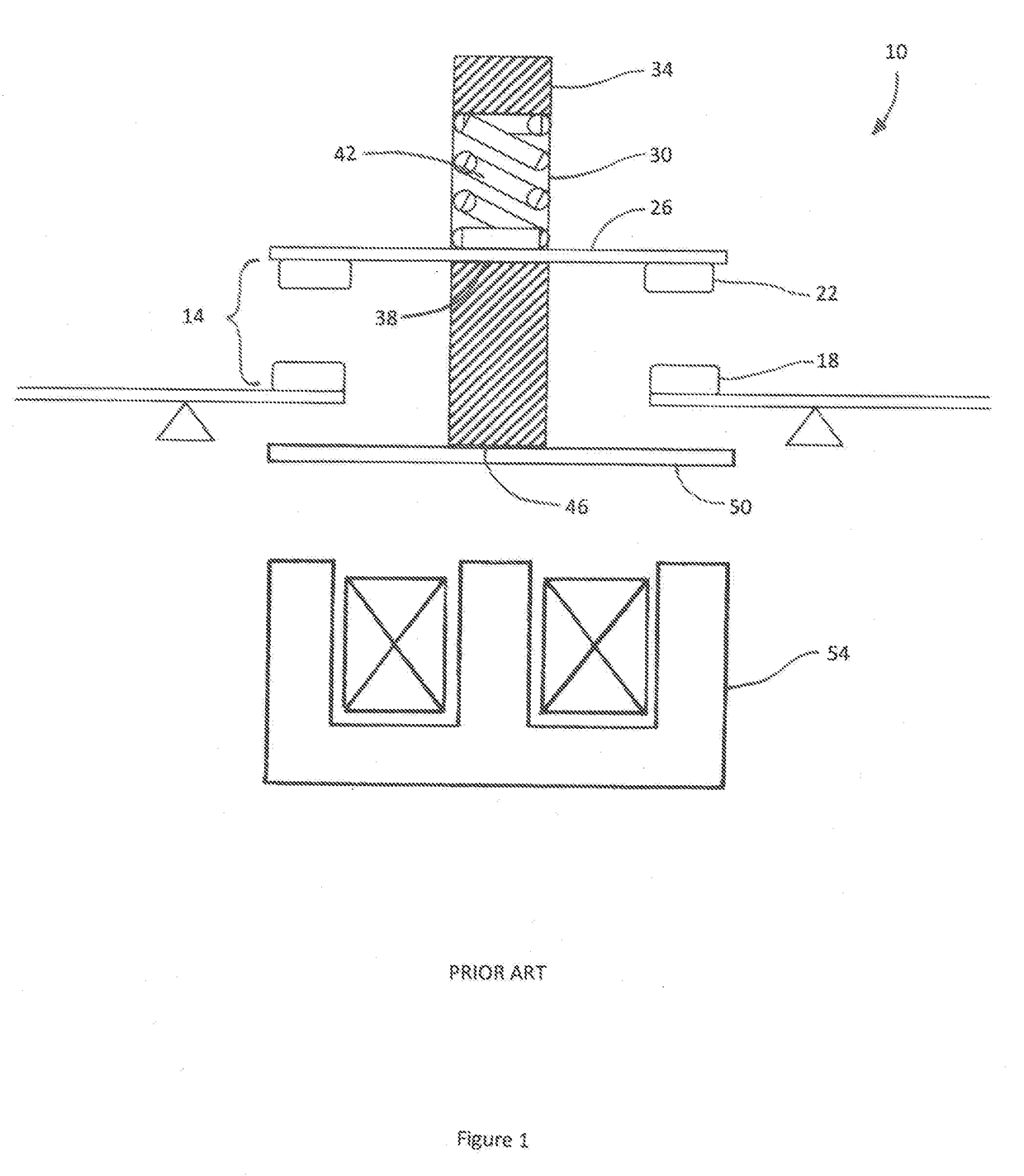
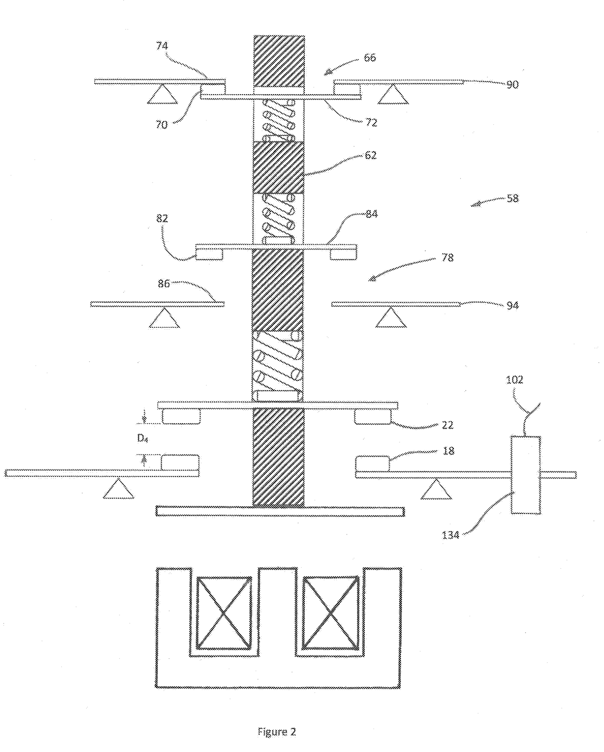
[0027]Referring now to FIG. 2, a contactor, generally represented by reference numeral 58, having the mechanical features for continuously monitoring the current condition of a power contact is illustrated in a stable OFF (OPEN) state where the fixed and movable power contacts, 18 and 22 respectively, are fully separated. The contactor 58 includes all of the elements of the state of the art contactor 10 as illustrated in FIG. 1 and new elements including a new contact carrier 62, a normally closed (NC) auxiliary contact 66 having movable contacts 70, supported on a bridge 72 and fixed contacts 74, and a normally open (NO) auxiliary contact 78 having movable contacts 82, supported on a bridge 84 and fixed contacts 86. The contact carrier 62 has been configured to support the movable NC auxiliary contacts 70 and the movable NO auxiliary contact 82, such that the movable NC auxiliary contacts 70 and the movable NO auxiliary contacts 82 move in unison with the movable power contacts 22....


PUM


Abstract

A method and apparatus for determining the current condition of power contacts and providing an indication to a preventive maintenance system and/or a user of required power contact replacement. The method includes auxiliary contacts providing a low power binary signal to a processor in response to movements of a contact carrier supporting the movable auxiliary contacts and movable power contacts. The low power binary signals, in combination with physical features of the contact carrier and a signal indicating the state of the power contact, provide information to the processor for determining the current condition of the power contacts, and if the current condition exceeds a predetermined limit, notifying the preventive maintenance system and/or the user.

Description

FIELD OF THE INVENTION[0001]The invention is generally directed to electric power contacts and particularly to preventive maintenance of equipment employing power contacts.BACKGROUND OF THE INVENTION[0002]The use of electrical contactors or other power control means that operate in a similar manner, as generally represented by reference numeral 10 in FIG. 1, for powering electrical equipment is well known. The contactor 10 includes a power contact 14, having one or more sets of two fixed power contacts 18, one being the input contact connected to a power source and the other being the output or load contact connected to equipment that will receive power from the power source. The contactor 10 also includes a set of two movable power contacts 22, electrically connected by a bridge 26, for each set of fixed power contacts 18. The fixed power contacts 18 are generally secured to a structural component of the contactor 10 such that they do not move. The bridge 26 of movable power contac...

Claims


Application Information

Patent Timeline
Patent Type & Authority Applications(United States)
IPC IPC(8): H01R13/66H01R13/08G01R19/165
CPCH01R13/6683G01R19/165H01R13/08G01R31/3278H01R13/7037H01R43/002
Inventor WEIDEN, CONRAD S.NGUYEN, HIEN M.MALONEY, MICHAEL V.CALLOWAY, SAMUEL JACOBARAZO, ANTHONY REAC MARTINEZ
Owner SCHNEIDER ELECTRIC USA INC
Why Eureka
Try Eureka