Electric heater

a heater and electric technology, applied in the field of electric heaters, can solve the problems of reducing the heating potential of ceramic heaters, negative influence of heat flow from the heater to the radiator elements, and reducing the voltage applied to ceramic heaters, so as to achieve better heat performan

Inactive Publication Date: 2018-11-15
MAHLE INT GMBH
View PDF7 Cites 2 Cited by
  • Summary
  • Abstract
  • Description
  • Claims
  • Application Information

AI Technical Summary

Benefits of technology

[0006]It is therefore an object of the present invention to provide an electric heater which has a better heat performance.
[0012]Furthermore, it is of advantage, that the heater, the contact elements and the insulation layers are arranged in a tube, wherein the radiator elements are located outside the tube thermally contacting the tube. Therefore the electrical connectable elements are safely located in a tube, which can be closed and sealed such that it is not compromised by dust, dirt or liquids. Furthermore, a tube is more stable against loads from outside the tube.
[0013]Furthermore, it is of advantage that the contact elements have metallic elements which elastically contact the heaters. Therefore the contact elements are able to withstand thermal expansion without loosing the electrical contact to the heater.
[0016]In order to create a safe and stable mechanic and electric connection to the heater, the contact elements can include metallic elements which are overmolded at their back with an electrically insulating plastic material. The overmolded plastic material increases the stability of the electrical contact element.

Problems solved by technology

Since the contact sheets are located between the heaters and the radiator elements they negatively influence the heat flow from the heater to the radiator elements.
This leads to a reduced heating potential of the ceramic heaters and this leads to the problem that the voltage applied to the ceramic heaters is not the nominal voltage.
This leads to problems to control the generated heat of the electric heater.

Method used


Image

  • Electric heater
  • Electric heater
  • Electric heater

Examples


Embodiment Construction

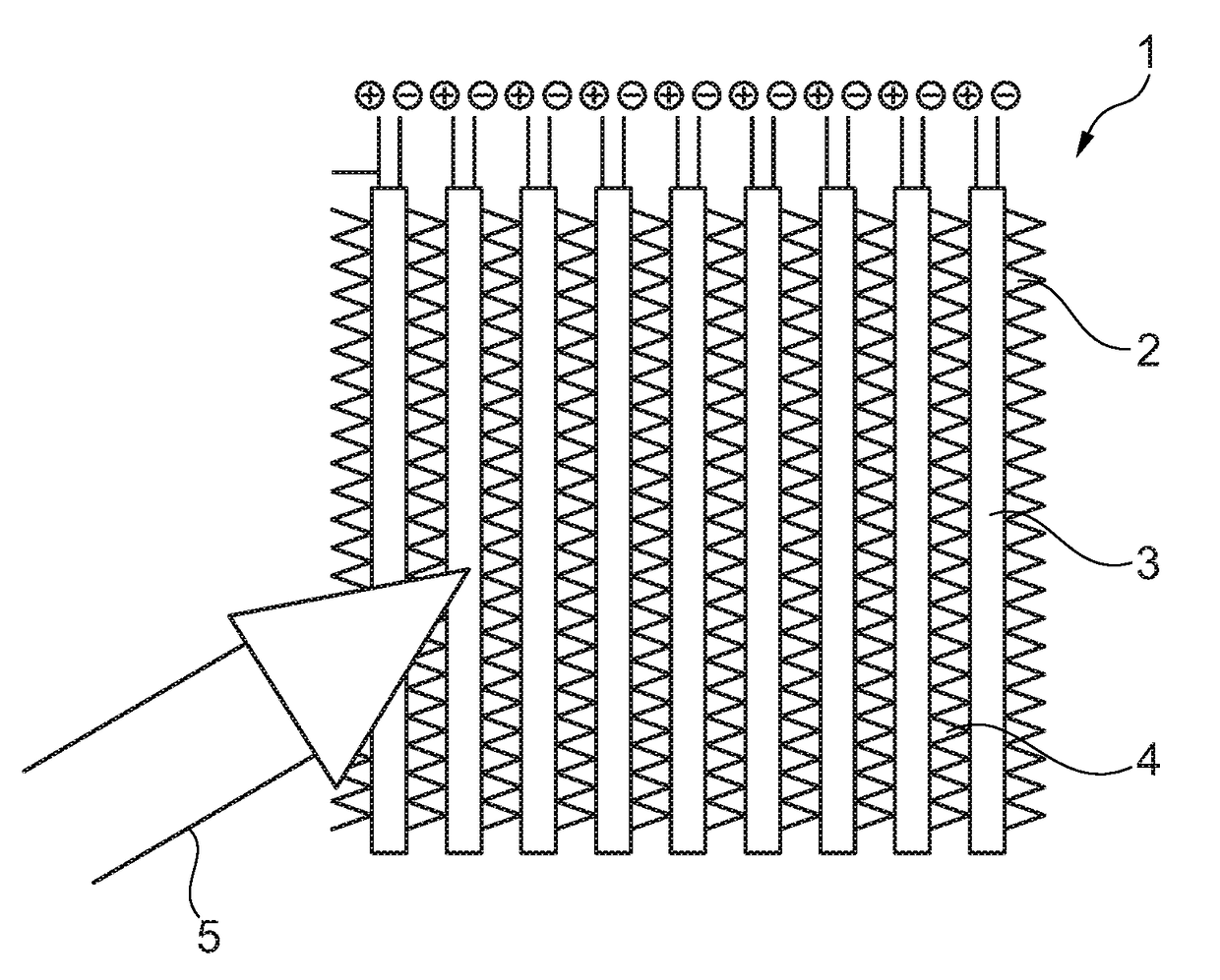
[0026]FIG. 1 shows an electric heater 1 with a heater core 2. The electric heater can be an electric heater for a heating or an air-conditioning system of a motor vehicle, for example. The electric heater can be an electric heater for other applications, e.g. for domestic applications.

[0027]The heater core 2 comprises a plurality of electric heating elements 3 and a plurality of radiator elements 4. The heating elements 3 are electrically heated due to an electrical current through the heater in the electrical heating element and the radiator elements 4 are transferring the generated heat to an air flow 5 which passes the radiator elements 4. The heater core 2 is made of a sandwich shaped arrangement of heating elements 3 and of radiator elements 4 such that the air flow 5 passing the radiator elements which are located in a space between two heating elements 3 respectively.

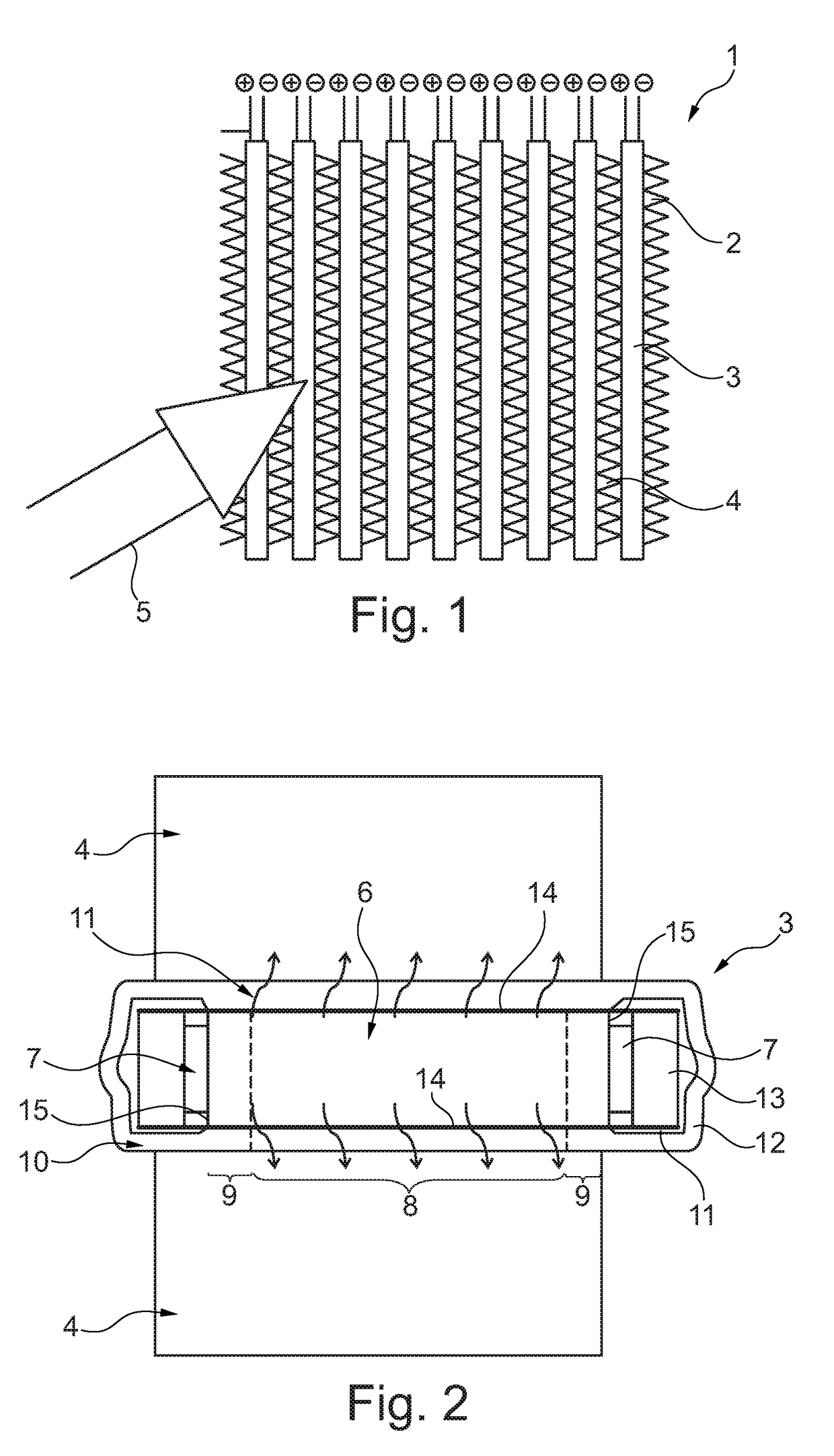
[0028]FIG. 2 shows a cross-sectional view of a heating element 3 with two radiator elements 4, which are locat...


PUM


Abstract

An electric heater in particular for a heating or an air-conditioning system of a motor vehicle, with a heater core having a plurality of electric heating elements having heaters and contact elements to electrically contacting the heaters, said heater core further having a plurality of radiator elements which thermally contact the heating elements, wherein the heater comprises a central portion and two lateral portions, wherein the central portion is arranged between the two lateral portions, wherein the radiator elements are thermally contacting the heater in a central portion and the contact elements are electrically contacting the heater in the lateral portions.

Description

[0001]This nonprovisional application claims priority under 35 U.S.C. § 119(a) to European Patent Application No. 17170947.0, which was filed in Europe on May 12, 2018, and which is herein incorporated by reference.BACKGROUND OF THE INVENTIONField of the Invention[0002]The present invention relates to an electric heater, in particular for a heating or an air-conditioning system of a motor vehicle, especially with an electrical and / or thermal engine, with a heater core comprising a plurality of electric heating elements comprising at least one heater and at least one contact to electrically contact the heater, said heater core further comprising a plurality of radiator elements which are thermally contacting the heater.Description of the Background Art[0003]Electric heaters are well known in the art especially for the use as a main heater or an auxiliary heater in a heating or an air-conditioning system of a motor vehicle.[0004]The electric heater is used for example to heat up an ai...

Claims


Application Information

Patent Timeline
Patent Type & Authority Applications(United States)
IPC IPC(8): B60H1/22
CPCB60H1/2225B60H1/2218B60H2001/00128B60H2001/2268B60H1/2215H05B3/02H05B3/10H05B2203/023F24H3/0429F24H9/1872F24H2250/04H05B2203/02H05B3/24
Inventor MISS, PASCALMAGNIER, GILLESMARLIER, ERIC
Owner MAHLE INT GMBH
Why Eureka
Try Eureka