Refrigerated Transport System with Refrigerant Dilution

a technology of refrigerant transport and refrigerant dilution, which is applied in the direction of transportation and packaging, domestic cooling equipment, lighting and heating equipment, etc., can solve the problems that refrigerants with low gwp may have higher flammability and/or toxicity levels than prior refrigerants

Inactive Publication Date: 2018-11-15
CARRIER CORP
View PDF14 Cites 12 Cited by
  • Summary
  • Abstract
  • Description
  • Claims
  • Application Information

AI Technical Summary

Benefits of technology

[0027]In one or more embodiments of any of the foregoing embodiments, a refrigerant charge of the vapor compression loop comprises at least 3% by weight propane.
[0028]In one or more embodiments of any of the foregoing embodiments, a refrigerant charge of the vapor compression loop comprises at least 50% by weight propane.
[0029]In one or more embodiments of any of the foregoing embodiments, the refrigerated transport system is a refrigerated intermodal shipping container wherein: the one or more doors comprise a pair of hinged doors at a first end of the body; and the refrigeration system is mounted in an equipment box at a second end of the body opposite the first end.
[0030]In one or more embodiments of any of the foregoing embodiments, the detector comprises a non-dispersive infrared sensor.
[0031]In one or more embodiments of any of the foregoing embodiments, a controller is coupled to the detector so as to, responsive to said detecting leakage of the refrigerant, at least one of: vent the refrigerated compartment; introduce a dilution gas from a gas source; lock at least one door of the one or more doors; isolate a portion of the refrigeration flowpath; and provide an audible and / or visible indication of the detection.
[0032]In one or more embodiments of any of the foregoing embodiments, a method for operating the refrigerated transport system comprises, responsive to said detecting leakage of the refrigerant, at least one of: venting the refrigerated compartment; introducing a dilution gas from a gas source; locking at least one door of the one or more doors; isolating a portion of the refrigeration flowpath; and providing an audible and / or visible indication of the detection.

Problems solved by technology

A number of proposed and possible future replacement refrigerants having low GWP also may have higher flammability and / or toxicity levels than prior refrigerants.

Method used


Image

  • Refrigerated Transport System with Refrigerant Dilution
  • Refrigerated Transport System with Refrigerant Dilution
  • Refrigerated Transport System with Refrigerant Dilution

Examples


Embodiment Construction

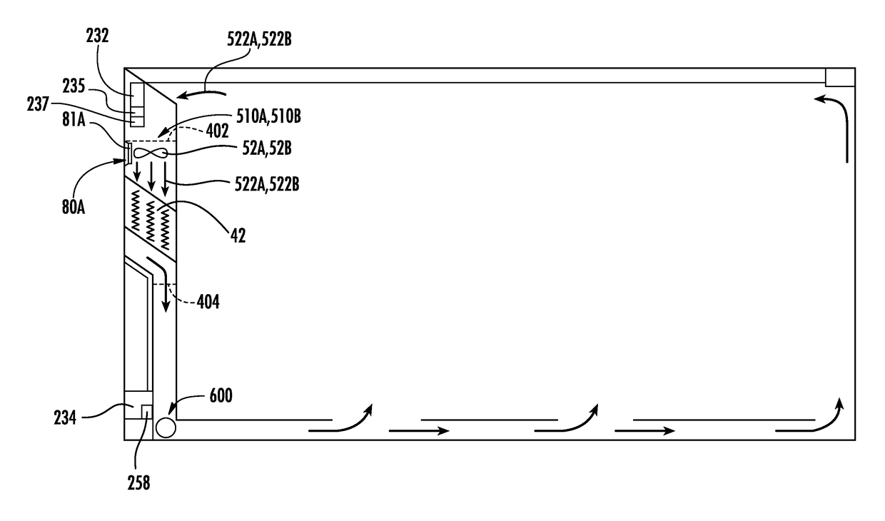
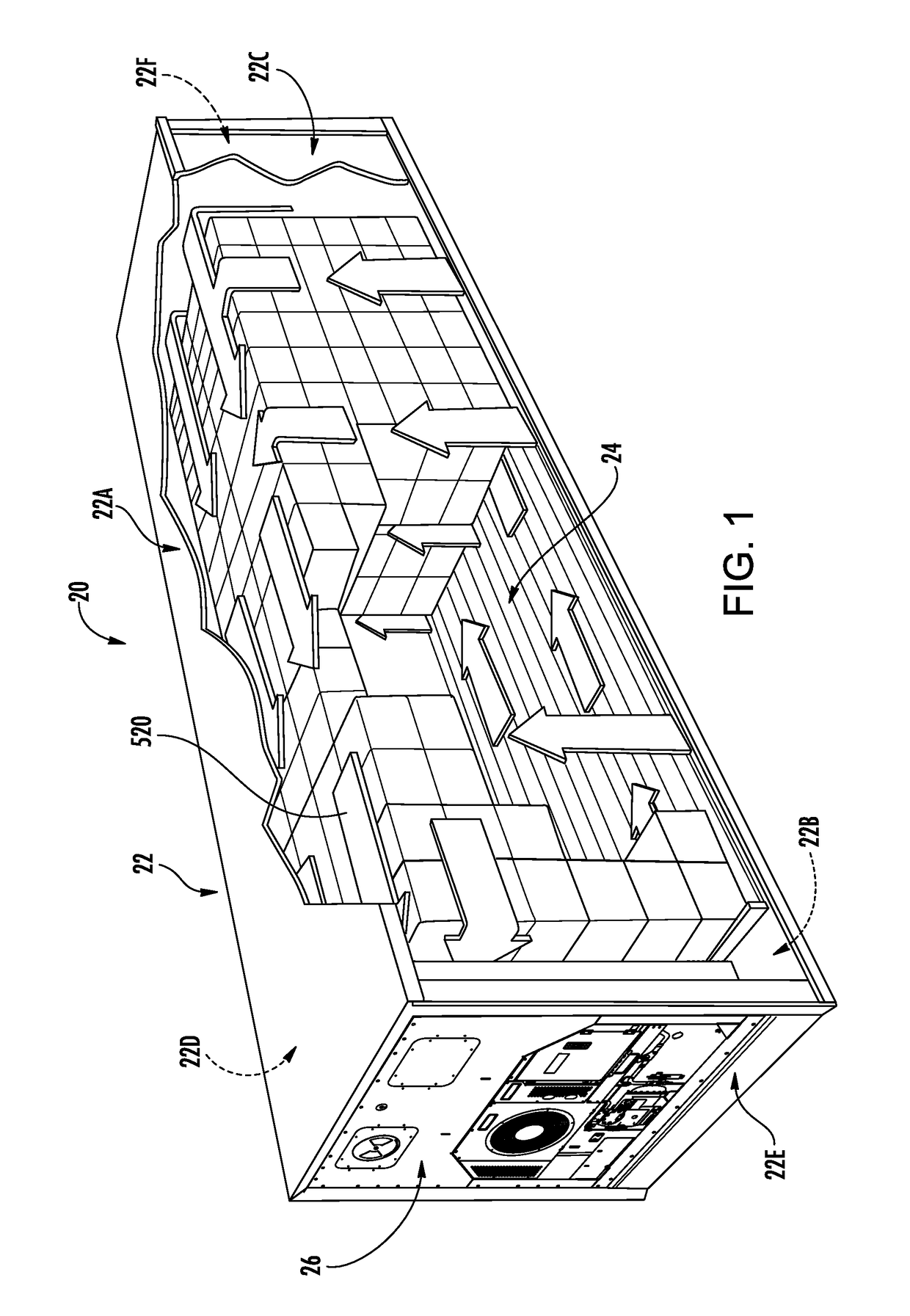
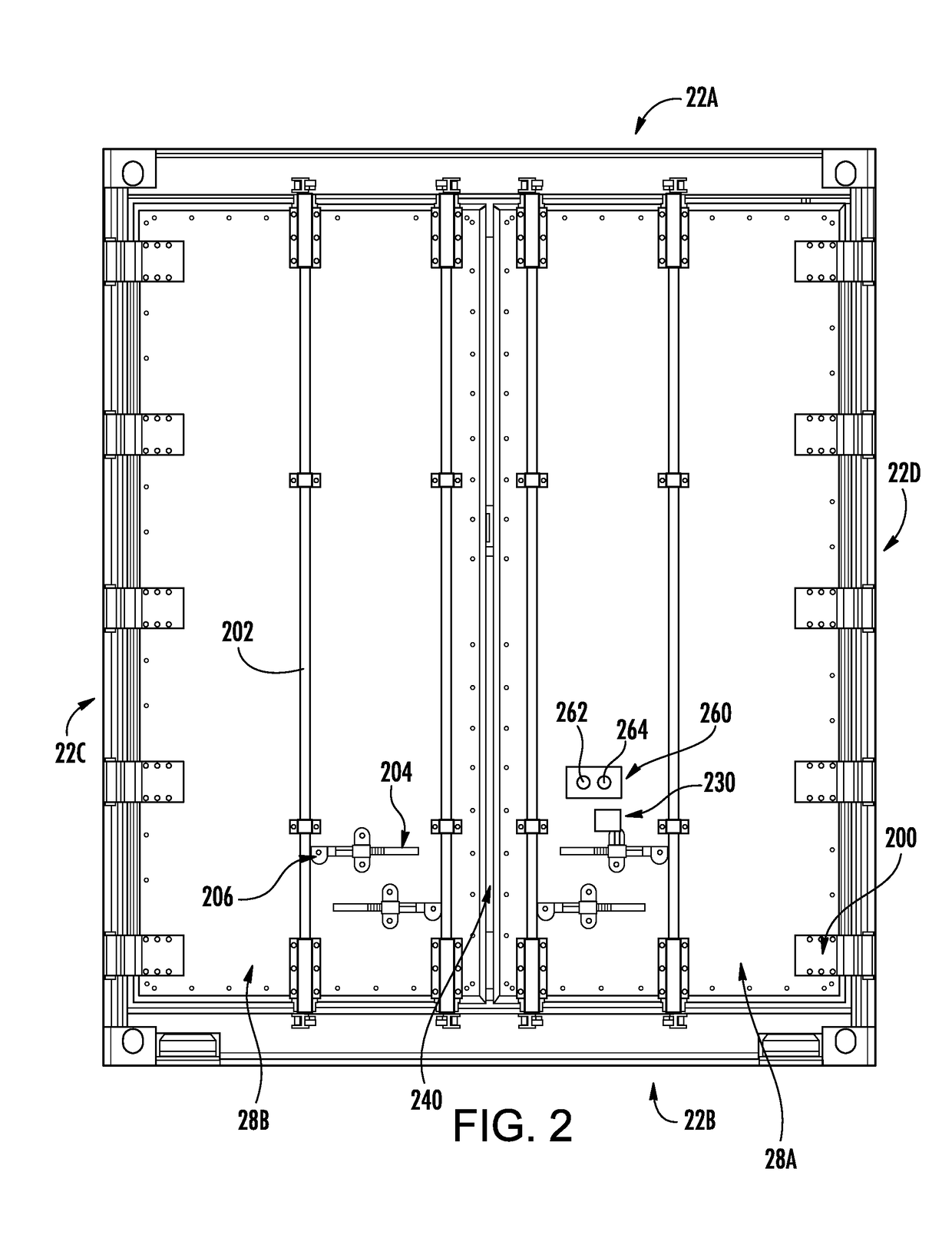
[0043]FIG. 1 shows an intermodal container 20 that may be shipped, trucked, trained or the like. The container has a body 22 enclosing an interior 24. The body and interior are formed essentially as right parallelepipeds. The body has a top 22A, a bottom 22B, a first side 22C, a second side 22D, a first end 22E and a second end 22F. The top, bottom, and sides may be an integral rigid metallic structural system. The first end may be closed by an equipment module 26 (“equipment box”). The second end may essentially be formed by a pair of oppositely hinged doors 28A, 28B (FIG. 2).

[0044]The equipment module contains a vapor compression refrigeration system 30 (FIG. 3). The illustrated example comprises, sequentially along a refrigerant flowpath 34, a compressor 36, a heat rejection heat exchanger 38, an expansion device 40 (e.g., electronic expansion valve, thermal expansion valve, orifice, or the like), and a heat absorption heat exchanger 42. One or more first fans 50 may drive an ext...


PUM


Abstract

A refrigerated transport system (20) comprises: a body (22) enclosing a refrigerated compartment. A refrigeration system (30) comprises: a charge of refrigerant; a compressor (36) for driving the refrigerant along a refrigerant flowpath (34); a first heat exchanger (38) along the refrigerant flowpath and positioned to reject heat to an external environment in a cooling mode; and a second heat exchanger (42) along the refrigerant flowpath and positioned to absorb heat from the refrigerated compartment in the cooling mode. The refrigerated transport system has a detector (232) for detecting leakage of the refrigerant.

Description

CROSS-REFERENCE TO RELATED APPLICATIONS[0001]Benefit is claimed of U.S. Patent Application No. 62 / 292,692, filed Feb. 8, 2016, and entitled “Refrigerated Transport System with Refrigerant Dilution” and U.S. Patent Application No. 62 / 253,070, filed Nov. 9, 2015, and entitled “Refrigerated Transport System with Refrigerant Safety”, the disclosures of which are incorporated by reference herein in their entirety as if set forth at length.BACKGROUND[0002]The disclosure relates to refrigerated transport systems such as intermodal containers. More particularly, the disclosure relates to refrigerant safety in such refrigerated transport systems.[0003]An exemplary refrigerated intermodal container (also known as a shipping container or intermodal shipping container) has an equipment module at one end of the container. The equipment module contains a vapor compression system having a compressor, a heat rejection heat exchanger downstream of the compressor along a refrigerant flow path, an exp...

Claims


Application Information

Patent Timeline
Patent Type & Authority Applications(United States)
IPC IPC(8): B65D88/74F25D11/00B65D90/00F25B49/00F25D29/00
CPCB65D88/745F25D11/003B65D90/008F25B49/005F25D29/003B60P3/20F25B2400/121F25B2500/222
Inventor PAPAS, PAULPOOLMAN, CIARA N.BURNS, LARRY D.RUSIGNUOLO, GIORGIOEDDY, RENEE A.DORMER, MICHAEL J.CHOPKO, ROBERT A.BURCHILL, JEFFREY J.RYDKIN, IVAN
Owner CARRIER CORP
Why Eureka
Try Eureka