Turbomachine Rotor Blade Tip Shroud Cavity

a technology of rotor blades and shrouds, which is applied in the field of turbomachines, can solve the problems of difficult or impossible to add conventional cavities to the tip shrouds, and the formation of conventional tip shroud cavities that require complex manufacturing processes

Active Publication Date: 2018-11-15
GENERAL ELECTRIC CO
View PDF4 Cites 0 Cited by
  • Summary
  • Abstract
  • Description
  • Claims
  • Application Information

AI Technical Summary

Benefits of technology

The present patent is about a rotor blade for a turbomachine and a turbomachine that includes the rotor blade. The rotor blade has an airfoil with a leading edge and a trailing edge, and a tip shroud that connects to the airfoil and has a leading edge wall and a trailing edge wall. The tip shroud cavity has a leading edge portion and a trailing edge portion that fluidly connect. This design allows for improved cooling of the rotor blade and better airflow. The technical effect of this design is improved efficiency and performance of the turbomachine.

Problems solved by technology

Nevertheless, conventional tip shroud cavities require complex manufacturing processes to form.
Furthermore, it may be difficult or impossible to add conventional cavities to the tip shrouds once the rotor blades are in service.

Method used


Image

  • Turbomachine Rotor Blade Tip Shroud Cavity
  • Turbomachine Rotor Blade Tip Shroud Cavity
  • Turbomachine Rotor Blade Tip Shroud Cavity

Examples


Embodiment Construction

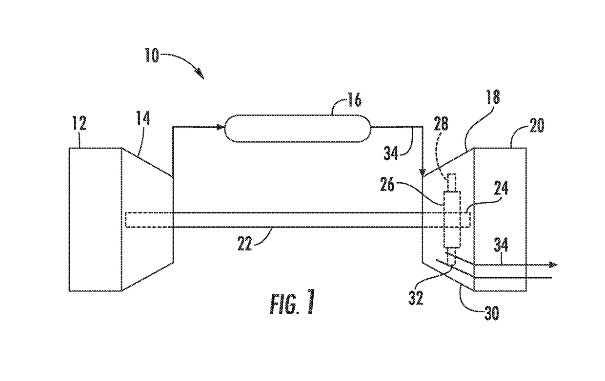
[0016]Reference will now be made in detail to present embodiments of the technology, one or more examples of which are illustrated in the accompanying drawings. The detailed description uses numerical and letter designations to refer to features in the drawings. Like or similar designations in the drawings and description have been used to refer to like or similar parts of the technology. As used herein, the terms “first”, “second”, and “third” may be used interchangeably to distinguish one component from another and are not intended to signify location or importance of the individual components. The terms “upstream” and “downstream” refer to the relative direction with respect to fluid flow in a fluid pathway. For example, “upstream” refers to the direction from which the fluid flows, and “downstream” refers to the direction to which the fluid flows.

[0017]Each example is provided by way of explanation of the technology, not limitation of the technology. In fact, it will be apparent...


PUM


Abstract

The present disclosure is directed to a rotor blade for a turbomachine. The rotor blade includes an airfoil having a leading edge and a trailing edge and defines a chord extending from the leading edge to the trailing edge. A tip shroud couples to the airfoil and includes a leading edge wall and a trailing edge wall and defines a tip shroud cavity. The tip shroud cavity includes a leading edge portion at least partially defined by the leading edge wall and positioned largely upstream of fifty percent of the chord. The tip shroud cavity also includes a trailing edge portion at least partially defined by the trailing edge wall and positioned largely downstream of fifty percent of the chord. An intermediate portion of the tip shroud cavity fluidly couples the leading edge portion of the tip shroud cavity and the trailing edge portion of the tip shroud cavity.

Description

FIELD[0001]The present disclosure generally relates to turbomachines. More particularly, the present disclosure relates to rotor blade tip shroud cavities for turbomachines.BACKGROUND[0002]A gas turbine engine generally includes a compressor section, a combustion section, a turbine section, and an exhaust section. The compressor section progressively increases the pressure of air entering the gas turbine engine and supplies this compressed air to the combustion section. The compressed air and a fuel (e.g., natural gas) mix within the combustion section and burn in a combustion chamber to generate high pressure and high temperature combustion gases. The combustion gases flow from the combustion section into the turbine section where they expand to produce work. For example, expansion of the combustion gases in the turbine section may rotate a rotor shaft connected, e.g., to a generator to produce electricity. The combustion gases then exit the gas turbine engine via the exhaust secti...

Claims


Application Information

Patent Timeline
Patent Type & Authority Applications(United States)
IPC IPC(8): F01D5/20F01D5/18F02C3/04
CPCF01D5/20F01D5/186F02C3/04F05D2220/32F05D2240/24F05D2260/202F05D2240/307F05D2250/11F05D2250/75F01D5/225
Inventor JONES, JEFFREY CLARENCEBRITTINGHAM, ROBERT ALAN
Owner GENERAL ELECTRIC CO
Why Eureka
Try Eureka