Pin Cover for an Inversion Table

a pin cover and inversion table technology, applied in the field of improvement of inversion table pin cover, can solve problems such as location creation, and achieve the effect of minimizing parts that can rub against each other

Active Publication Date: 2018-11-29
PENA DONROBERT
View PDF1 Cites 5 Cited by
  • Summary
  • Abstract
  • Description
  • Claims
  • Application Information

AI Technical Summary

Benefits of technology

[0012]It is an object of the pin cover for an inversion table to be fixed with the frame of the inversion table. Fixing the cover to the inversion table minimizes parts that can rub against each other. Rubbing parts cause wear and create locations where an object, such as a towel can follow the rubbing parts and can get caught in the sliding connection. Fixing the cover to the fixed frame further fixes the orientation of the cover to protect any openings.
[0013]It is an object of the pin cover for an inversion table to have an opening for the moving frame that supports the table to freely move within the opening. The opening is oriented away from the user whereby the rotational motion of the moving table frame is away from the user and they are restricted from placing a finger in the opening. The opening is further oriented to prevent fluids from entering into the pin engagement area. While this prevents fluids from entering into the housing it further blocks objects from falling vertically into the cover.
[0015]It is another object of the pin cover for an inversion table for the pin cover to be fabricated one or more housing parts. In one contemplated embodiment the cover is made as two halves or clam shells, but as few as one to more than two housing parts are contemplated. A first shell secures to the fixed frame and the second shell is placed around the moving frame member and is then secured to the first clam shell. The two clam shell parts have overlapping surfaces to provide a seal from debris and fluid from fluid that enter into the housing.
[0016]It is still another object of the pin cover for an inversion table to have a protective lip that covers the shank of an inserted pin. The cover protects inadvertent movement of the pin and further blocks objects, such as a towel, from coming in contact with the pin shank.

Problems solved by technology

Rubbing parts cause wear and create locations where an object, such as a towel can follow the rubbing parts and can get caught in the sliding connection.

Method used


Image

  • Pin Cover for an Inversion Table
  • Pin Cover for an Inversion Table
  • Pin Cover for an Inversion Table

Examples


Embodiment Construction

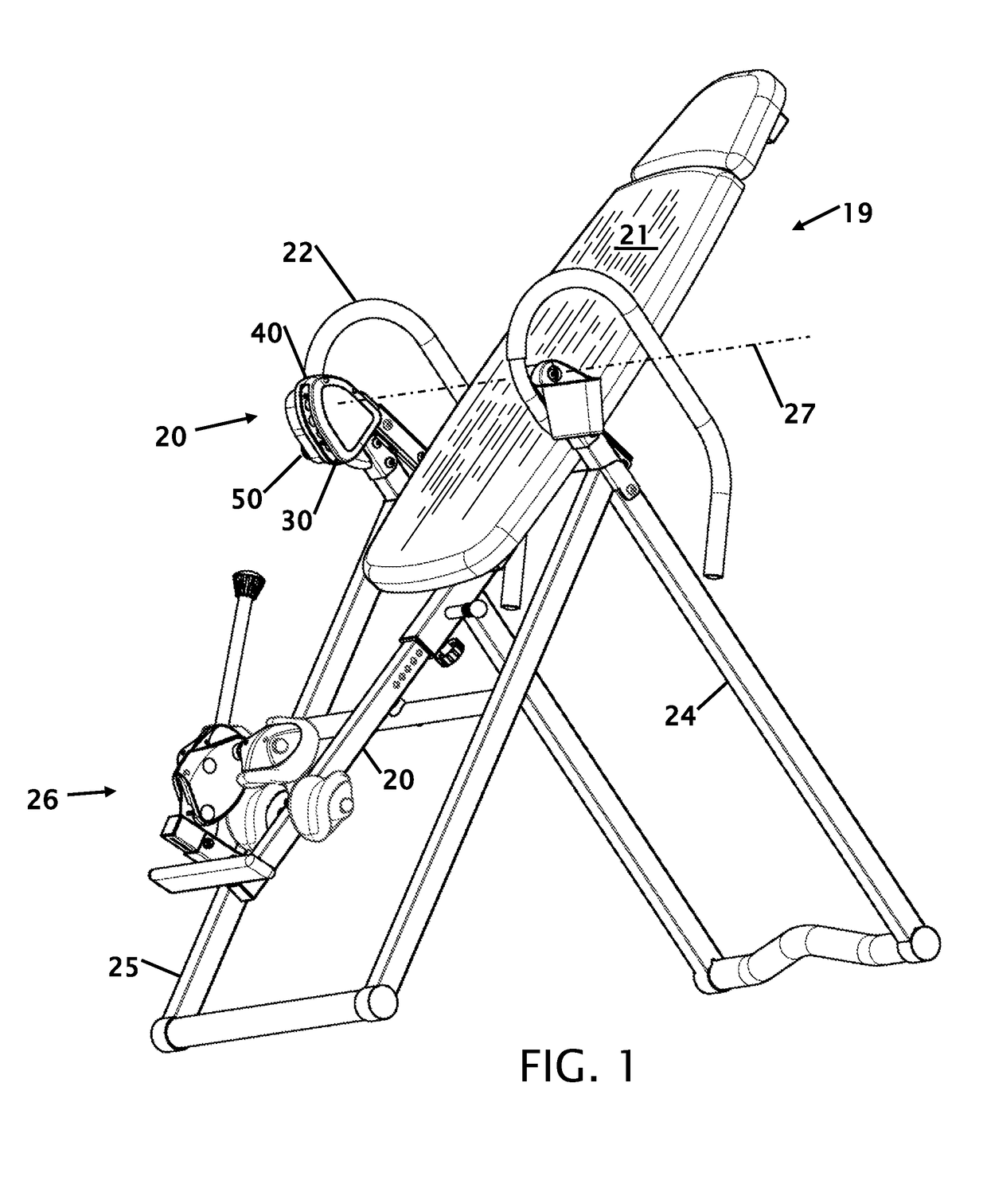
[0025]FIG. 1 shows a perspective view of an inversion table 19 with the pin cover 20. An inversion table 19 allows a person to invert themselves to reduce back stress and elongate the spine. To use an inversions table 19 a person locks their legs in the ankle holder 26. The ankle holder 26 is typically located on an adjustable frame member that allows the person to establish a desired center pivot for the rotational axis 27. Once they are secured, the user can use the arm / hand tubes 22 to invert themselves through pivot axis 27. The inversion table 21 is supported on a table pivot frame 23.

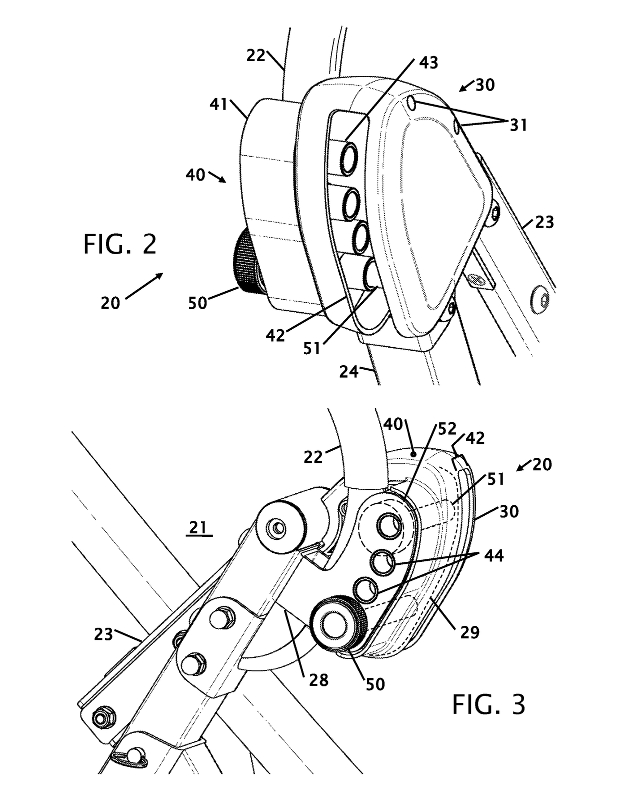
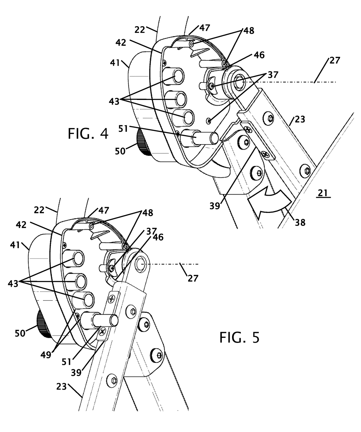
[0026]The table pivot frame 23 is secured through bearings to the main frame having a rear leg 24 and a front leg 25. The rotation of the inversion table 19 bed 21 is restricted with a pin 50 that passes through the fixed frame and prevents additional rotation of the table pivot frame 23. Because of the relationship of the table pivot frame 23, the pin 50 and the fixed frame, there is a potential ...


PUM


Abstract

Improvements in a cover for a pin used in an inversion table that prevents the inversion table from rotating beyond a desired amount of rotation. The cover is secured to the fixed frame and has a slot for the rotating frame to move within the slot. The cover prevents debris, sweat, body parts, towels or clothing from entering into the locking pin area. The cover makes the inversion table safer to operate by covering a pinch-point where the rotating component of the inversion table contacts the rotation stop. The cover can take a variety of shape and material configurations to provide the coverage and protection for the user of the inversion table.

Description

CROSS REFERENCE TO RELATED APPLICATION[0001]Not ApplicableSTATEMENT REGARDING FEDERALLY SPONSORED RESEARCH OR DEVELOPMENT[0002]Not ApplicableTHE NAMES OF THE PARTIES TO A JOINT RESEARCH AGREEMENT[0003]Not ApplicableINCORPORATION-BY-REFERENCE OF MATERIAL SUBMITTED ON A COMPACT DISC[0004]Not ApplicableBACKGROUND OF THE INVENTIONField of the Invention[0005]This invention relates to improvements in a pin cover for an inversion table. More particularly, the present cover encloses the pinch points where a pin is used to limit rotation of an inversion table.Description of Related Art Including Information Disclosed Under 37 CFR 1.97 and 1.98[0006]Inversion tables have been used for many years by people to reduce back pain and to stretch the spine. Inversion tables are essentially beds, tables or a cloth covered frame. The table is secured to a frame across the narrow mid-section of the table to allow the table to pivot across the mid-section. At one end of the table is a retention mechanis...

Claims


Application Information

Patent Timeline
Patent Type & Authority Applications(United States)
IPC IPC(8): A61H1/02A63B26/00
CPCA61H1/0292A63B26/00A61H2203/0493A61H2205/081A63B2023/006
Inventor PENA, DONROBERT
Owner PENA DONROBERT
Why Eureka
Try Eureka