Water storage apparatus

a technology for water storage apparatus and water filter jugs, which is applied in the field of filtering, storage and cooling of liquids, can solve the problems of many possible sources of contamination, limited storage, and undesirable for a domestic water filter jug to occupy an excessive amount of space within a refrigerator, so as to minimise the size of the base portion, minimise the weight of the part to be carried, and improve the effect of stability

Inactive Publication Date: 2005-07-14
STRIX LTD
View PDF15 Cites 7 Cited by
  • Summary
  • Abstract
  • Description
  • Claims
  • Application Information

AI Technical Summary

Benefits of technology

[0049] If the vessel is of a cordless arrangement the power supply unit may, in one embodiment, be located within an enclosure in the lower portion of the portable jug portion. This minimises the size of the base portion.
[0050] In an alternative embodiment the power supply unit is provided in the base portion of the appliance. This minimises the weight of the part to be carried and also give greater stability and minimises the chance of base pickup which can be a problem with some cordless connectors.
[0051] It has been appreciated that by the Applicant that by locating the power supply unit in the base portion of the appliance only a low voltage DC power supply is provided to the jug portion. Thus a lower specification cordless connector could be used than would be required for a mains connector. Preferably, however, a standard cordless connector is used such as the Applicant's P72 range of 360° C. cordless connectors in order to minimise costs.

Problems solved by technology

Although domestic water is often strictly regulated so as to be fit for drinking, there are many possible sources of contamination.
Since domestic refrigerators are generally of a compact size the storage available is limited.
Thus, it is undesirable for a domestic water filter jug to occupy an excessive amount of space within a refrigerator.
Even if a user chooses a limited capacity jug for storing in a refrigerator, the space occupied by the filter jug within the refrigerator is still likely be inconvenient.
One problem with this proposal, which has been identified by the Applicant, is the location of the Peltier device in the base of the cup.
This does not provide an efficient cooling mechanism.
Whilst this may not be too significant in a small cup-sized device, which is primarily intended to maintain the initial temperature of a drink contained in it, the Applicant has appreciated that such a flaw could significantly compromise the effectiveness of an apparatus for bulk cooling of a larger body of water to reduce its temperature.

Method used


Image

  • Water storage apparatus
  • Water storage apparatus
  • Water storage apparatus

Examples


Embodiment Construction

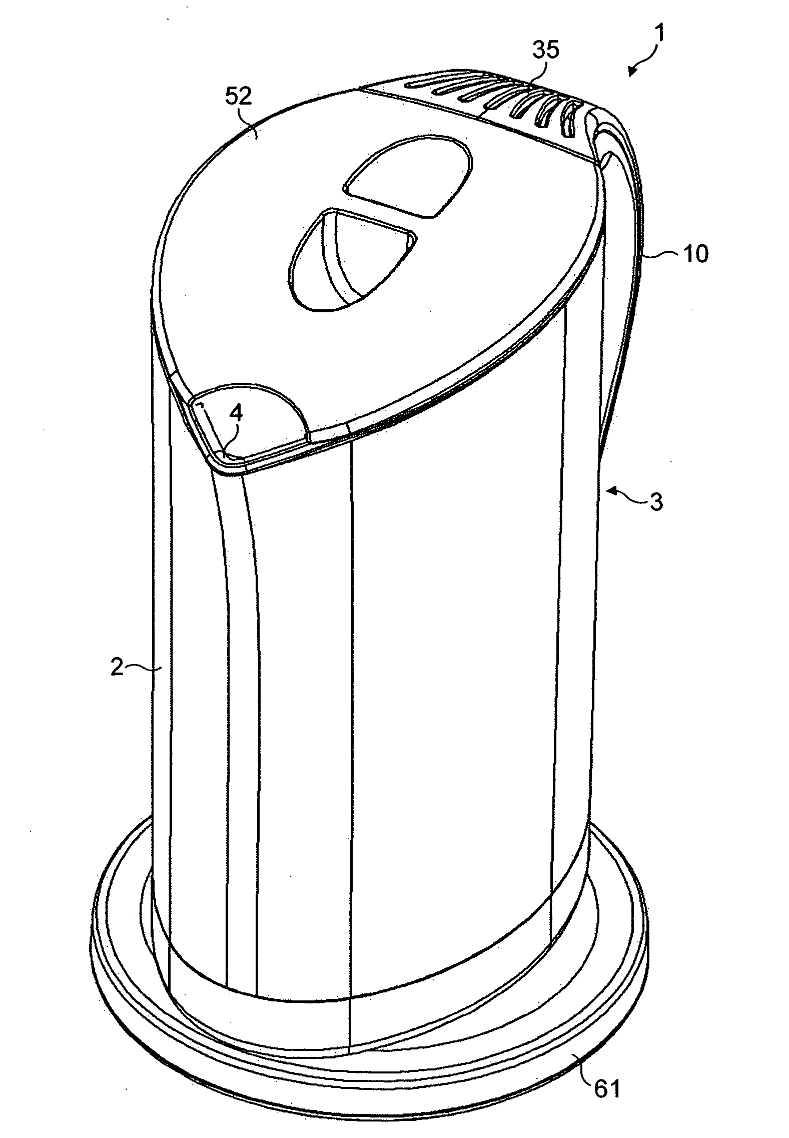
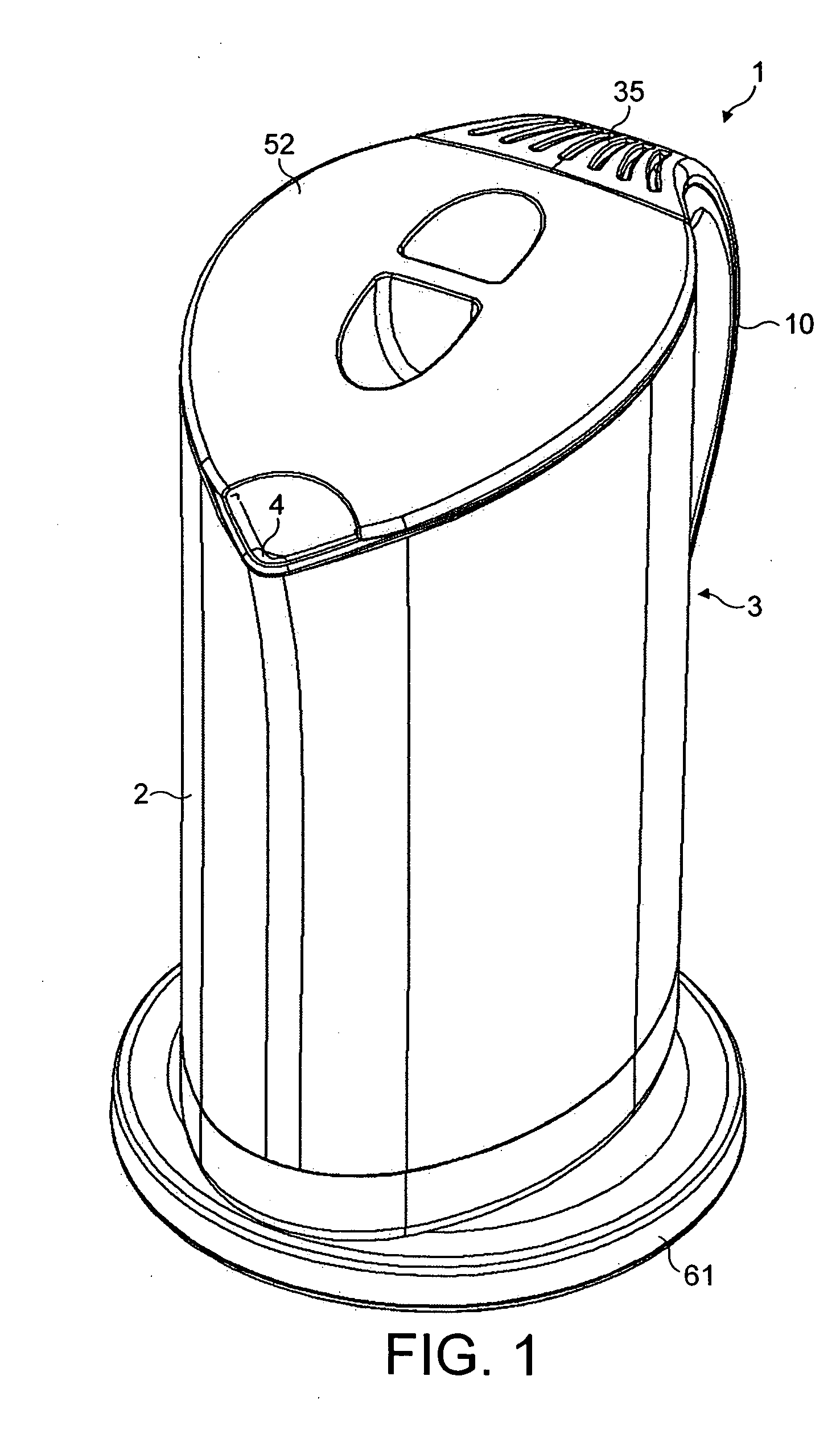
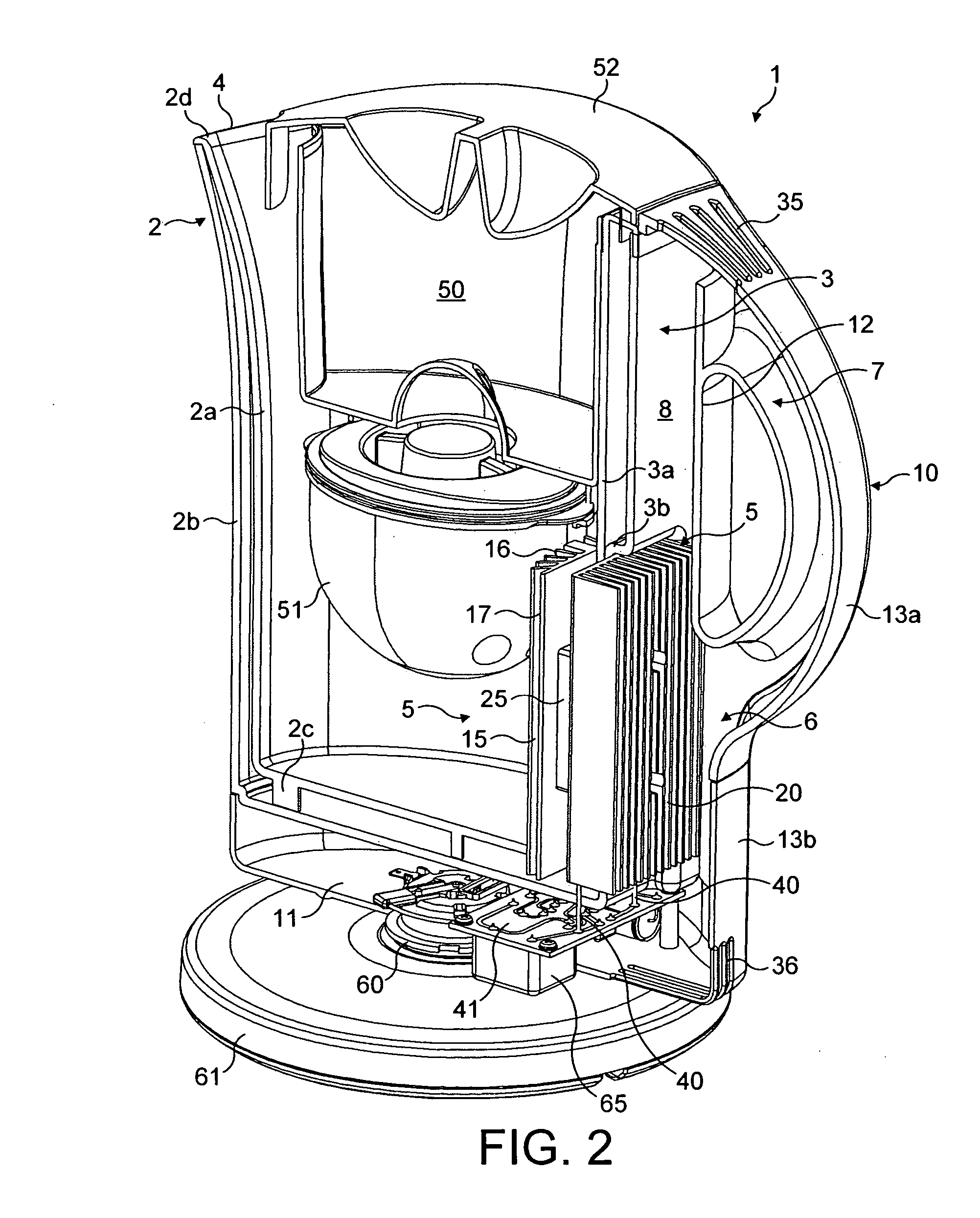
[0066] A preferred embodiment of the present invention will now be described with reference to FIGS. 1, 2 and 3. A jug device for filtering, storing and cooling water is shown generally by the reference numeral 1. The jug comprises a plastics main vessel portion 2, similar to those known for use in domestic jug kettles, and a cooling means 5. As known in the art of filter jugs, the jug 1 further comprises a reservoir 50 for untreated water which locates in the upper portion of the main vessel 2, a filter 51 in fluid communication with the reservoir 50 and a lid 52.

[0067] The main vessel 2 is arranged so that a side wall 3 has a substantially flat profile while the other side walls are curved to form a conventional, generally elliptical jug shape with a spout 4 provided opposite the flat wall 3. The flat wall 3 provides a location for the cooling means 5. The flat side wall 3 is also the wall to which the handle 10 is attached. Such an arrangement is similar to known jug kettle desi...


PUM

PropertyMeasurementUnit
temperatureaaaaaaaaaa
thermally insulatingaaaaaaaaaa

Abstract

A water treatment and storage vessel has a reservoir for untreated water and filter means in fluid communication with the reservoir. A main vessel portion is provided for receiving and storing treated water which comprises a Peltier-effect device for removing heat from treated water therein, thereby cooling the water.

Description

CROSS REFERENCE TO RELATED APPLICATIONS [0001] This application claims the benefits of prior filed, co-pending foreign patent applications GB 0323237.8 filed Oct. 3, 2003 and GB 0404293.3 filed Feb. 27, 2004. BACKGROUND OF THE INVENTION [0002] 1. Technical Field [0003] The present invention relates to the filtering, storage and cooling of liquids, particularly water, in domestic contexts. [0004] 2. Background Information [0005] Although domestic water is often strictly regulated so as to be fit for drinking, there are many possible sources of contamination. Consumer concerns about the potential aesthetic and health related problems resulting from the presence of these contaminants has promoted the development of home water treatment systems to improve the quality of the water supply. Such systems can reduce the presence of common contaminants resulting in clearer, safer and better tasting and smelling water for household use. [0006] Typically domestic water filtration is carried out...

Claims


Application Information

Patent Timeline
Patent Type & Authority Applications(United States)
IPC IPC(8): A47J27/21A47J41/00C02F1/00F25B21/02F25D31/00
CPCA47J27/21183A47J41/005C02F1/003C02F2201/006F25D2331/809F25B21/02F25B2321/0251F25D31/006C02F2307/04
Inventor SCOTT, MICHAEL JAMES
Owner STRIX LTD
Why Eureka
Try Eureka