
Ceramic matrix composite (CMC) turbine blade assembly, dovetail sleeve, and method of mounting cmc turbine blade

a turbine blade and composite technology, applied in blade accessories, machines/engines, mechanical equipment, etc., can solve the problems of high area that is required on each pressure face, large fillet from the airfoil that transitions to these pressure faces, and risk of lock-up at the flank angl

Active Publication Date: 2018-11-29
GENERAL ELECTRIC CO
View PDF2 Cites 3 Cited by
  • Summary
  • Abstract
  • Description
  • Claims
  • Application Information

AI Technical Summary

Benefits of technology

The invention is about a ceramic matrix composite (CMC) turbine blade assembly and a dovetail sleeve used to secure the blade to a rotor. The dovetail sleeve has inner and outer surfaces that contact the root and slot surfaces of the blade to hold it in place. The technical effect of this invention is that it provides a reliable and secure mounting mechanism forCMC blade assemblies in turbines, ensuring optimal performance and durability.

Problems solved by technology

As a result, the area that is required on each pressure face is high, and the fillet from the airfoil that transitions to these pressure faces may be large.
A lower flank angle on the CMC dovetail increases fillet and interlaminar tension (ILT) stresses and increases wear concerns due to a higher normal force, but there is a risk of lock up for higher flank angles.

Method used


Image

  • Ceramic matrix composite (CMC) turbine blade assembly, dovetail sleeve, and method of mounting cmc turbine blade
  • Ceramic matrix composite (CMC) turbine blade assembly, dovetail sleeve, and method of mounting cmc turbine blade
  • Ceramic matrix composite (CMC) turbine blade assembly, dovetail sleeve, and method of mounting cmc turbine blade

Examples


Embodiment Construction

[0015]Provided is a ceramic matrix composite (CMC) turbine blade assembly, a dovetail sleeve, and a method of mounting a CMC turbine blade.

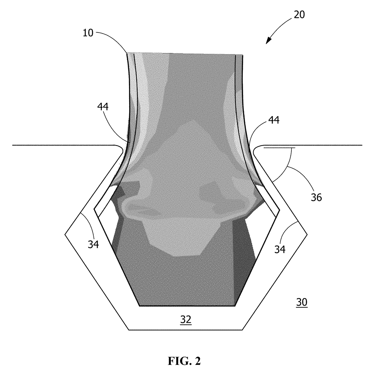
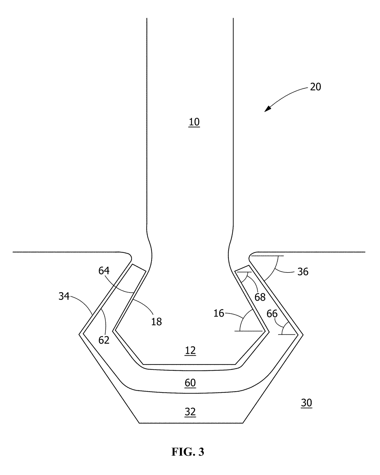
[0016]Embodiments of the present disclosure, for example, in comparison to concepts failing to include one or more of the features disclosed herein, decrease fillet stresses, decrease interlaminar stresses, decrease interlaminar tension (ILT) in the CMC turbine blade, reduce wear on the rotor, reduce the maximum dovetail thickness, reduce normal forces, reduce material costs, promote locking during operation, reduce the risk of lockup during operation, increase rotor tang next section thickness, or combinations thereof.

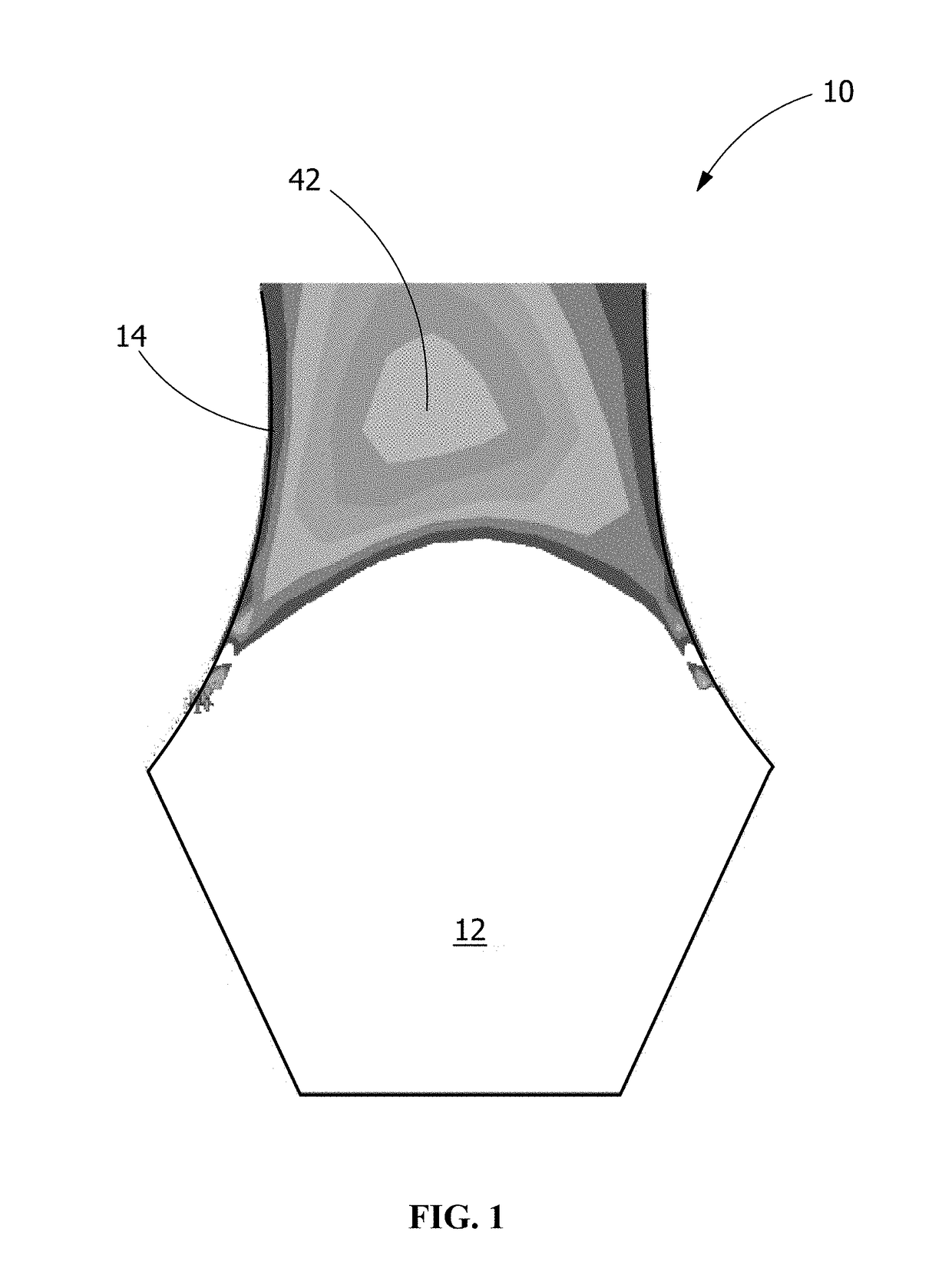
[0017]Referring to FIG. 1, the CMC turbine blade 10 includes a dovetail root 12 and a narrowed neck region 14. The shading in the narrowed neck region 14 represents the amount of interlaminar tension (ILT) in the CMC turbine blade 10, with an area of maximum ILT 42 shown in the middle of the narrowed neck region 14. Only a lower po...


PUM


Abstract

A ceramic matrix composite (CMC) turbine blade assembly includes a rotor, a CMC turbine blade, and at least one dovetail sleeve. The rotor has a blade slot with at least one slot surface. The slot surface is at a slot angle. The CMC turbine blade is received in the blade slot. The CMC turbine blade includes a dovetail root having at least one root surface. The root surface is at a root angle. The root angle is at least 5 degrees greater than the slot angle. The dovetail sleeve is received in the blade slot of the rotor. The dovetail sleeve has at least one inner surface contacting at least one root surface and at least one outer surface contacting at least one slot surface to radially retain the CMC turbine blade in the blade slot. A dovetail sleeve and a method of mounting a CMC turbine blade are also disclosed.

Description

FIELD OF THE INVENTION[0001]The present embodiments are directed to ceramic matrix composite (CMC) turbine blade assemblies. More specifically, the present embodiments are directed to dovetail sleeves and CMC turbine blade assemblies including dovetail sleeves.BACKGROUND OF THE INVENTION[0002]The manufacture of a ceramic matrix composite (CMC) part typically includes laying up pre-impregnated composite fibers having a matrix material already present (prepreg) to form the geometry of the part (pre-form), autoclaving and burning out the pre-form, infiltrating the burned-out pre-form with the melting matrix material, and any machining or further treatments of the pre-form. Infiltrating the pre-form may include depositing the ceramic matrix out of a gas mixture, pyrolyzing a pre-ceramic polymer, chemically reacting elements, sintering, generally in the temperature range of 925 to 1650° C. (1700 to 3000° F.), or electrophoretically depositing a ceramic powder. With respect to turbine air...

Claims


Application Information

Patent Timeline
Patent Type & Authority Applications(United States)
IPC IPC(8): F01D5/28F01D5/30
CPCF01D5/282F05D2300/6033F05D2230/60F01D5/3007F01D5/284F01D5/30F01D25/00F01D5/3084F01D5/28F01D25/285
Inventor KITTLESON, JACOB JOHNDELVAUX, JOHN MCCONNELL
Owner GENERAL ELECTRIC CO
Learn More