Automatic rainfall measurement system

Inactive Publication Date: 2018-11-29
SOLTANI FARIBORZ
View PDF0 Cites 10 Cited by
  • Summary
  • Abstract
  • Description
  • Claims
  • Application Information

AI Technical Summary

Benefits of technology

[0026]In the present invention, the electronic circuitry which measures rainfall does not depend on the electromechanical system, which rotates the container of the rain gauge. As a result, mechanical malfunctions caused by temperature fluctuations, fatigue or the presence of dust on the pivots or joints will not affect the accuracy of the rain gauge. Besides, since external objects such as dust, leaf, feather, etc can neither enter the container of the rain gauge nor block the opening of the collector of the rain gauge, the accuracy of the rain gauge is not in

Problems solved by technology

Consequently, the system won't be activated when the r

Method used


Image

  • Automatic rainfall measurement system
  • Automatic rainfall measurement system
  • Automatic rainfall measurement system

Examples


Embodiment Construction

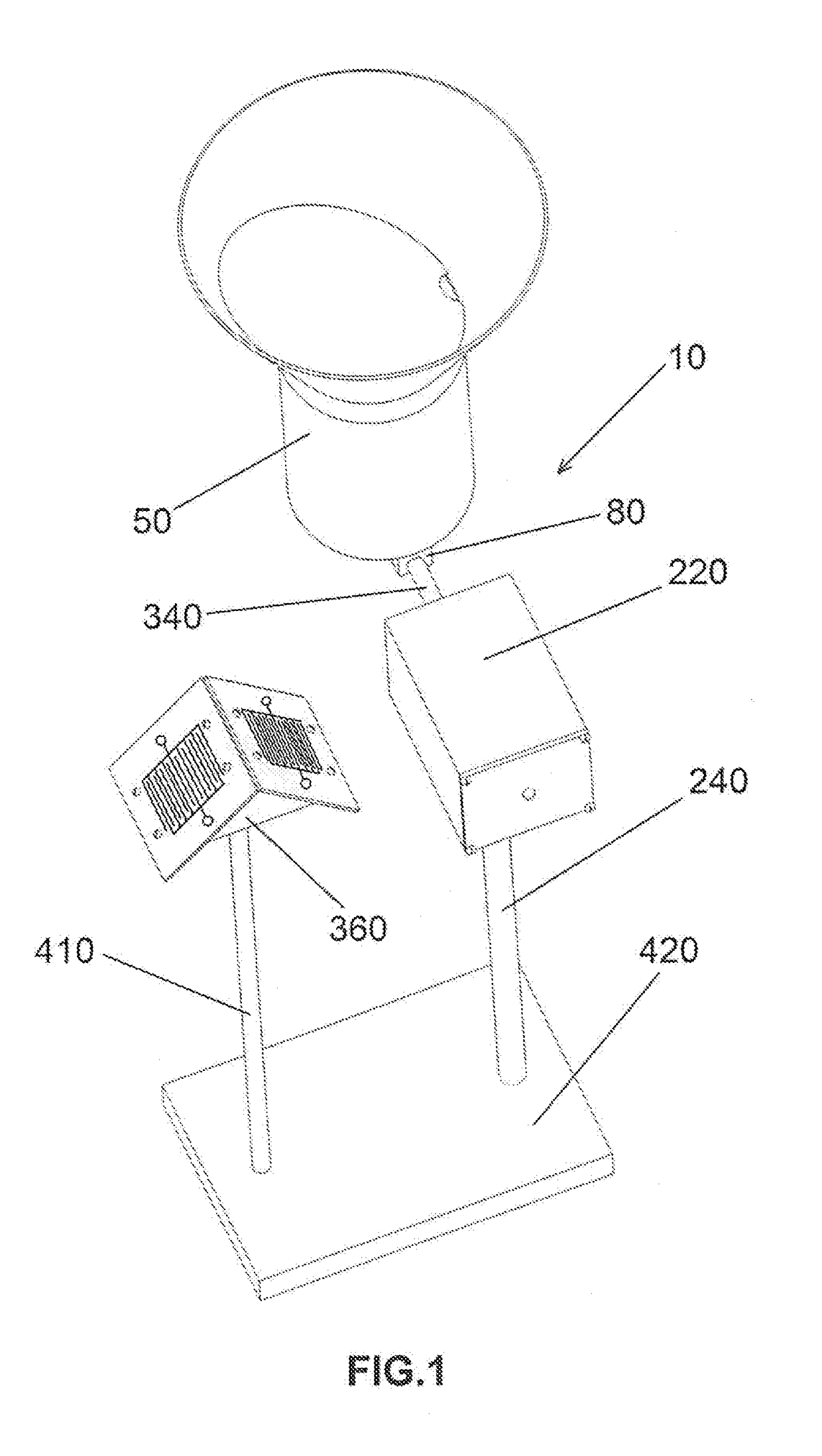
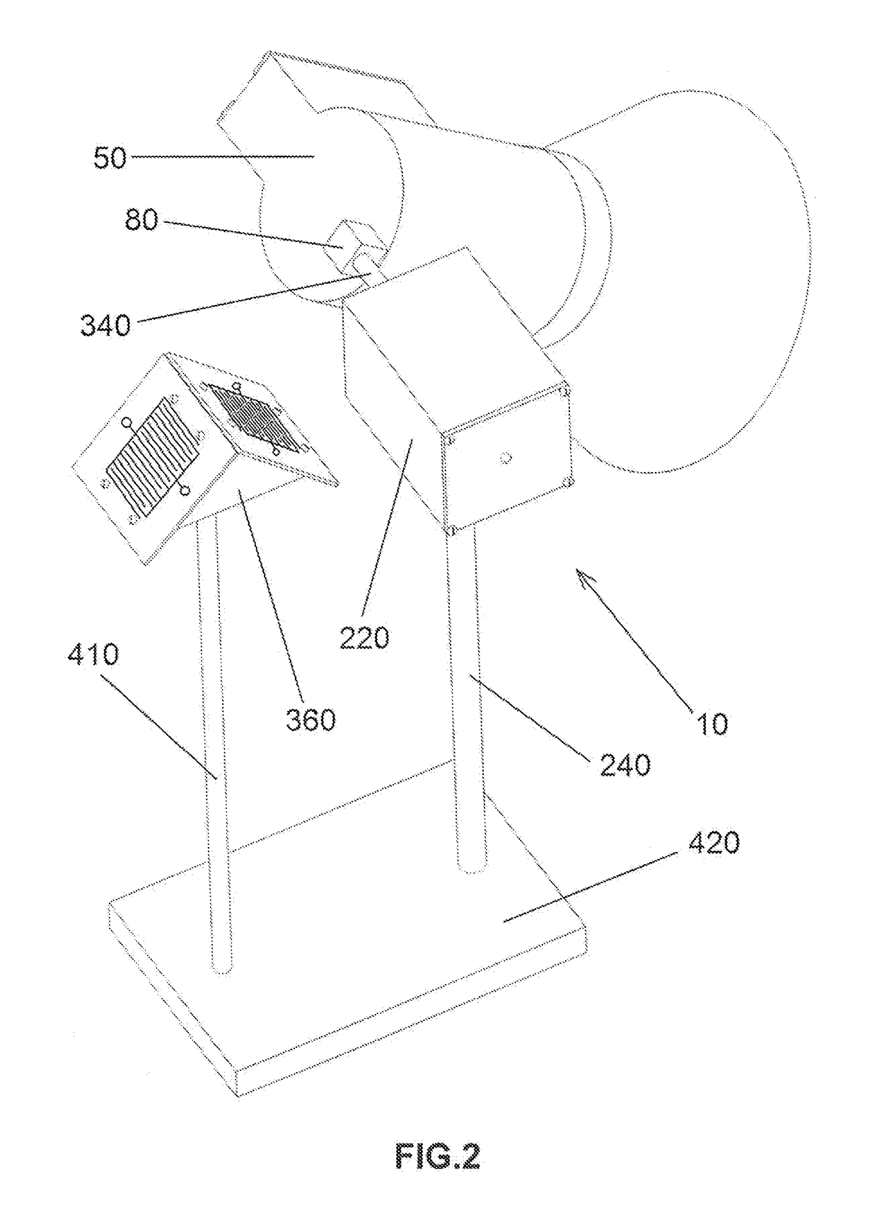
[0054]The first embodiment of the present invention 10, which has been illustrated in FIG. 1 and FIG. 2, comprises a rain gauge 50, a rain detector 360 a base 420, and a motor housing 220, which includes an electric motor 310 with a gearbox 330, an encoder 320, and part of the control circuitry 430. The rain gauge 50 of the first embodiment of the system 10, which will be described in details, is attached to the motor shaft 340 through a shaft mount 80, which is fixed to the bottom 140 of the rain gauge 50. The motor housing 220 and the rain detector 360 can be permanently or temporarily fixed to the base 420 through support rods 240 and 410. That is, the support rods 240 and 410 may be screwed or welded to the base 420 or they may be a permanent part of the base 420.

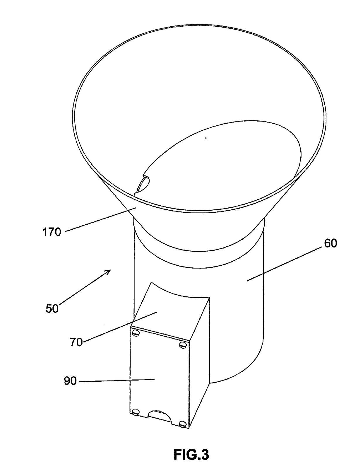
[0055]The rain gauge 50 of the first embodiment of the system 10, which has been shown in FIG. 3 and FIG. 4, comprises a container 60 with a shaft mount 80, a collector 170, and a circuit housing 70 with a lid 90. The c...


PUM


Abstract

An automatic rainfall measurement system with a set of control circuitry measures the height of rainwater or any other conductive liquid by means of a plurality of conductors attached to the wall of the container of the system's rain gauge. A rain detector detects falling raindrops and sends an electrical signal to the control circuitry of the rain gauge. Consequently, an electromechanical system rotates the container of the rain gauge from its initial downward facing position to its final vertical position so that the rain gauge starts collecting raindrops and measuring rainfall. After that it stops raining, and the final height of the rainwater is measured, the electromechanical system rotates the container of the rain gauge back to its initial downward facing position so that the rainwater inside the container is drained away by the gravitational force.

Description

[0001]The invention described herein may be manufactured and used by the Government of the United States of America and the Government of the Jewish State of Israel for governmental purposes without the payment of any royalties thereon.TECHNICAL FIELD[0002]The present invention relates generally to devices and systems for measuring liquid level and more specifically to automatic rain gauges.BACKGROUND OF THE INVENTION[0003]Various dictionaries have presented slightly different definitions for the word “rainfall”. Some dictionaries define the word “rainfall” as the amount of rain that falls in a place during a particular period. A few dictionaries define it as the amount of precipitation usually measured by the depth in inches. Others define the word “rainfall” as the amount of rain that falls. In this patent, the word “rainfall” refers to the latter definition. That is, in this patent, the word “rainfall” only refers to the amount of rain that falls and does not refer to the period ...

Claims


Application Information

Patent Timeline
IPC IPC(8): G01W1/14
CPCG01W1/14G01N21/85G01F23/241
Inventor SOLTANI, FARIBORZ
Owner SOLTANI FARIBORZ
Why Eureka
Try Eureka