
Device and method for adjusting the rate and correcting the state of display of a watch

a technology of display rate and display device, which is applied in the direction of clock support device, horology, instruments, etc., can solve the problems of continuous display time drift and inability to control the display

Active Publication Date: 2018-11-29
THE SWATCH GRP RES & DEVELONMENT LTD
View PDF0 Cites 5 Cited by
  • Summary
  • Abstract
  • Description
  • Claims
  • Application Information

AI Technical Summary

Benefits of technology

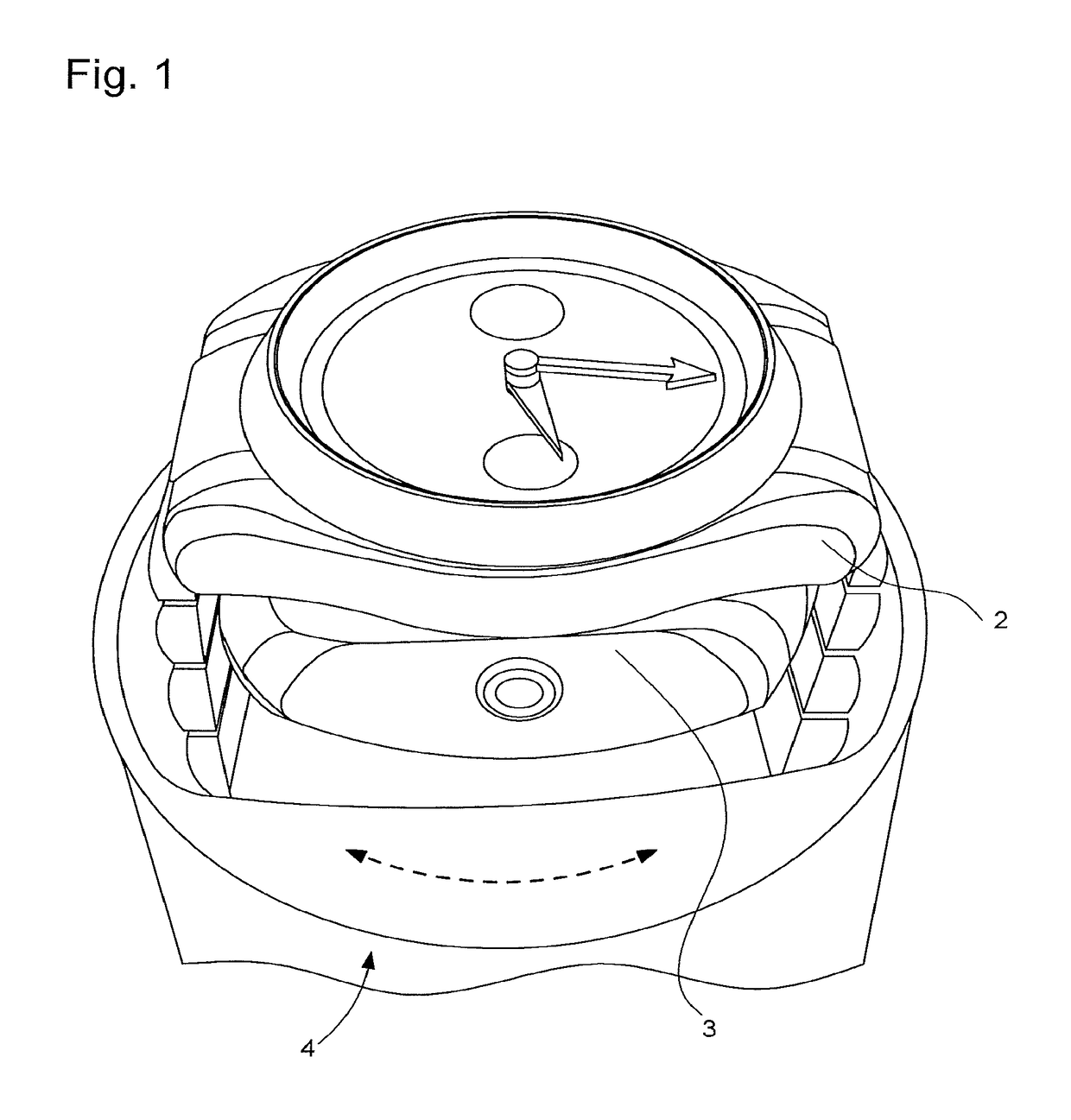
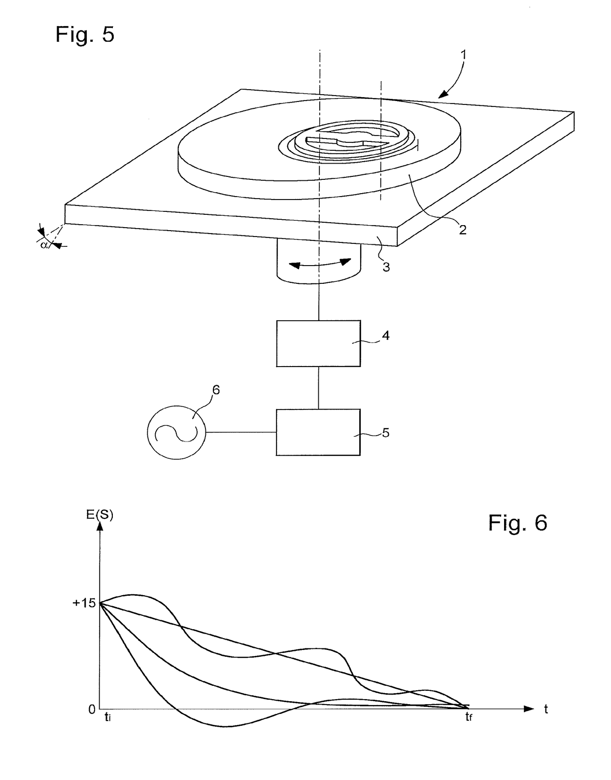
The invention proposes a method and device for controlling the frequency of a watch or movement with an oscillator. The device includes a support that fixes the watch or movement to a reference time base. The support imparts an oscillating motion to the watch or movement, which imposes a reference frequency on its balance spring or oscillator. The invention aims to achieve a periodic back and forth motion of the entire watch without removing it from its case to control its frequency. The invention also concerns a state of display correction device for correcting the display of a watch or movement, and an interactive support device for correction of a watch or movement. The invention further concerns the use of a rate adjustment and state of display correction device and an automatic winder for mechanical or automatic watches. The technical effects of the invention include improved accuracy and control of watch or movement frequency, improved display correction, and improved user experience.

Problems solved by technology

Automatic winders are designed for winding mechanical or automatic or manual watches, but simply move the oscillating weight, or rotate the crown, to rewind the barrel, without correcting either the rate or the state of the watch.
When the user leaves his watch for a long time on such a winder, the displayed time drifts continuously and in an uncontrolled manner.

Method used


Image

  • Device and method for adjusting the rate and correcting the state of display of a watch
  • Device and method for adjusting the rate and correcting the state of display of a watch
  • Device and method for adjusting the rate and correcting the state of display of a watch

Examples


Embodiment Construction

[0045]It is proposed here to control, by means of a servo device, the frequency of at least one watch, or respectively a mechanical movement, having at least one oscillator, referred to hereafter as a ‘basic oscillator’ to differentiate it from so-called ‘absolute’ oscillators which can generate references, more particularly absolute references, and from oscillators that will be referred to as ‘master oscillators’, of intermediate quality between absolute oscillators and basic oscillators. A very high precision clock, which does not form part of the invention, but to which reference is made, may form a reference clock, with an absolute oscillator generating a reference frequency.

[0046]The invention applies equally to a timepiece, which may be a complete watch, a watch head or a movement. To simplify the description, the term “watch” will be used indiscriminately to designate any of these entities. Anything that applies to an entire watch is directly applicable to an entire movement,...


PUM


Abstract

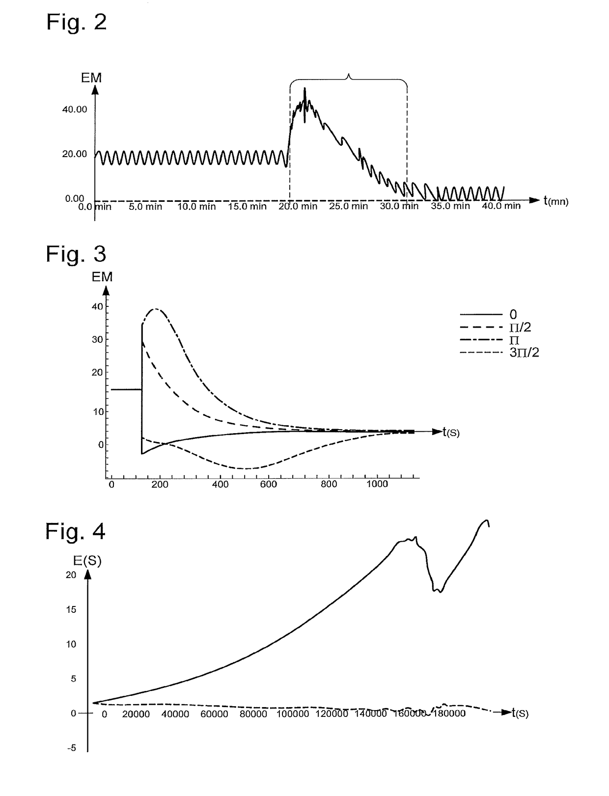
Method for adjusting the rate of a basic oscillator of a watch arranged to oscillate at a nominal frequency N0, with a master oscillator generating an excitation frequency NE approximately equal to an integer multiple of this nominal frequency N0, the master oscillator subjecting the watch to excitation or a modulated motion during a transition phase after which the basic oscillator is stabilised at the excitation frequency NE, and a state of display correction method with a winder for mechanical or automatic watches, moving a support carrying the watch and comprising a state of display correction oscillator, having a lower variation of rate value than the initial variation of rate value DI of this basic oscillator, and oscillating at a correction frequency NC to impose oscillation or a motion on the watch, during a state of display correction phase whose duration is adjusted to exactly correct a state of display error measured at the initial moment of actuation.

Description

[0001]This application claims priority from European Patent Application No. 17173302.5 filed on May 29, 2017, the entire disclosure of which is hereby incorporated herein by reference.FIELD OF THE INVENTION[0002]The invention concerns a method for correcting the state of display of a watch or respectively a movement, said watch or respectively said movement comprising at least one basic oscillator arranged to generate oscillation at a nominal frequency.[0003]The invention also concerns a method for adjusting the rate and correcting the state of display of a watch or respectively a movement, said watch or respectively said movement comprising at least one basic oscillator arranged to generate oscillation at a nominal frequency.[0004]The invention concerns a state of display correction device for correcting the state of display of a watch or respectively a movement, said watch or respectively said movement comprising at least one basic oscillator arranged to generate oscillation at a ...

Claims


Application Information

Patent Timeline
IPC IPC(8): G04B17/00
CPCG04B17/00G04D1/063G04D7/1264G04C13/028G04D7/1278G04B17/20A44C5/0007G04B18/02G04B5/00
Inventor FAVRE, JEROMEWILLEMIN, MICHELBORN, JEAN-JACQUESLECHOT, DOMINIQUEDI DOMENICO, GIANNI
Owner THE SWATCH GRP RES & DEVELONMENT LTD
Learn More