
Aerial inventory antenna

a technology of inventory scanning and antennas, applied in the direction of instruments, non-resonant long antennas, sensing by electromagnetic radiation, etc., can solve problems such as disassembly of customer relationships, and achieve the effects of low cost, low cost and low cos

Active Publication Date: 2018-11-29
ADASA
View PDF0 Cites 7 Cited by
  • Summary
  • Abstract
  • Description
  • Claims
  • Application Information

AI Technical Summary

Benefits of technology

The present invention solves important problems for retail stores that use RFID inventory counting and localization for omnichannel retailing. These stores need to ensure that they have accurate inventory information to avoid customer relationship issues when promising delivery or pickup of items that are not actually in stock. The invention meets eight solution criteria, including push-button inventory, safety, high availability, quiet operation, minimal disturbance to sales floor, centimeter location accuracy, and low capital expense. The invention eliminates propellers that can interfere with the shopping process, and uses a mechanical apparatus to lift the RFID scanning antenna to various altitudes. Compared to large arrays of fixed RFID readers, the invention has lower capital expense and can read RFID tags over a greater area.

Problems solved by technology

In these highly competitive retail environments such as this, inventory errors can result in disastrous customer relationship problems when a retailer promises delivery or pickup of an item that is not actually in stock, ready to hand over to a waiting customer.

Method used


Image

  • Aerial inventory antenna
  • Aerial inventory antenna
  • Aerial inventory antenna

Examples


Embodiment Construction

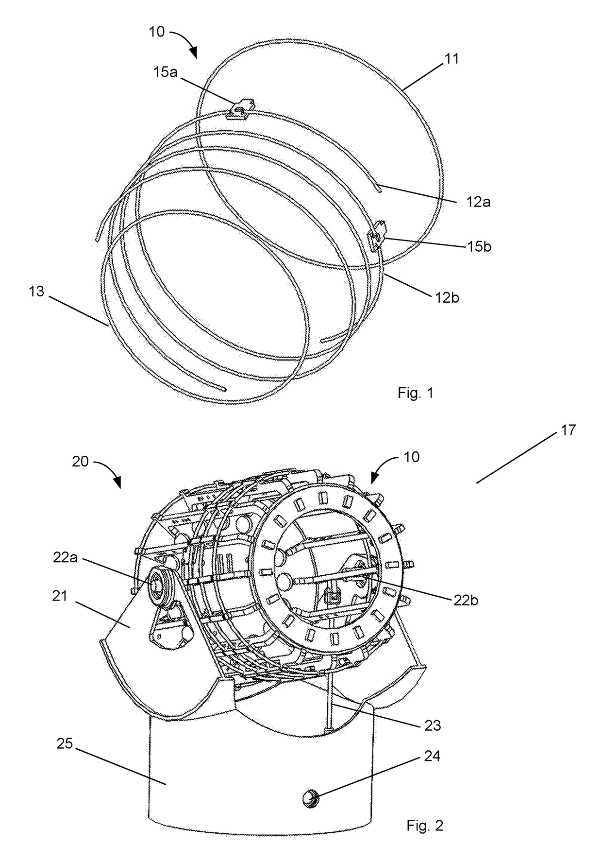
[0030]Making reference to various figures of the drawings, possible embodiments of the present invention are described and those skilled in the art will understand that alternative configurations and combinations of components may be substituted without subtracting from the invention. Also, in some figures certain components are omitted to more clearly illustrate the invention, similar features share common reference numbers.

[0031]To clarify certain aspects of the present invention, certain embodiments are described in a possible environment—as identification means for retail items that are bought and used by consumers. In these instances, certain methods make reference to items such as clothing, garments, shoes, consumables, electronics, and tires, but other items may be used by these methods. Certain embodiments of the present invention are directed for identifying objects using RFID transponders in supply chains, retail stores, warehouses, and distribution centers—both indoors an...


PUM


Abstract

The present invention teaches a frequency-scalable high-gain dual-polarization radio beam application platform for private, public, government, or military radio applications such as RFID (radio frequency identification), aerial and robotic inventory scanning, radio communications, telemetry, telecommand, aeronautical radionavigation, radiolocation, earth exploration, space research for terrestrial, air-to-ground, space-to-earth, or space-to-space uses.

Description

RELATED APPLICATIONS[0001]The present application is a continuation-in-part application of co-pending U.S. patent application Ser. No. 15 / 691,739 filed 30 Aug. 2017 which is a continuation-in-part application of U.S. patent application Ser. No. 15 / 286,560 filed 6 Oct. 2016 which is U.S. Pat. No. 9,780,435 and of expired U.S. patent application Ser. No. 14 / 311,215 filed 20 Jun. 2014 that claim priority and benefit based on U.S. patent application Ser. No. 13 / 693,026 filed on 3 Dec. 2012 by the same inventor Clarke W. McAllister. The present application also claims priority and benefit under 35 USC Section 119(e) of U.S. Provisional Application No. 62 / 238,105 filed on 6 Oct. 2015 all by the same inventor Clarke W. McAllister, the disclosures of which are expressly incorporated herein by reference. Also the following filed 7 May 2014, and 61 / 567,117 filed 5 Dec. 2011, and 61 / 677,470 filed 30 Jul. 2012, and 61 / 708,207 filed 1 Oct. 2012, and of 61 / 709,771 filed 4 Oct. 2012, all by the sa...

Claims


Application Information

Patent Timeline
IPC IPC(8): H01Q1/22H01Q1/28H01Q7/00H01Q1/36H01Q19/02G06K7/10
CPCH01Q1/2216H01Q1/28H01Q7/00H01Q1/362H01Q19/021G06K7/10346G06Q10/087H01Q11/08H01Q19/28
Inventor MCALLISTER, CLARKE WILLIAM
Owner ADASA
Learn More