
Apparatus and method for angular and rotational additive manufacturing

a technology of additive manufacturing and apparatus, applied in the direction of additive manufacturing, mechanical equipment, turbines, etc., can solve the problems of limited size of objects to be built, limited scan quality, and limited size of powder beds

Inactive Publication Date: 2018-12-06
GENERAL ELECTRIC CO
View PDF6 Cites 39 Cited by
  • Summary
  • Abstract
  • Description
  • Claims
  • Application Information

AI Technical Summary

Benefits of technology

The present invention relates to an additive manufacturing apparatus that can produce objects by depositing powder and directing an irradiation beam to fuse the powder. The apparatus includes a build platform, a powder delivery mechanism, and an irradiation beam directing mechanism. The build platform can rotate, and the powder delivery mechanism has two gates to control powder dispensation. The invention also provides a method for manufacturing objects using the apparatus. The technical effects of the invention include improved precision and accuracy in the manufacturing process, as well as the ability to produce objects with complex shapes.

Problems solved by technology

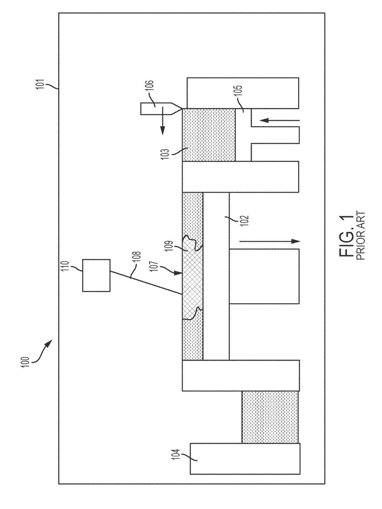
However, since the build needs to take place in the powder bed, the size of object to be built is limited by the size of the machine's powder bed.
Increasing the size of the powder bed has limits due to the needed large angle of incidence that can lower scan quality, and weight of the powder bed which can exceed the capabilities of steppers used to lower the build platform.

Method used


Image

  • Apparatus and method for angular and rotational additive manufacturing
  • Apparatus and method for angular and rotational additive manufacturing
  • Apparatus and method for angular and rotational additive manufacturing

Examples


Embodiment Construction

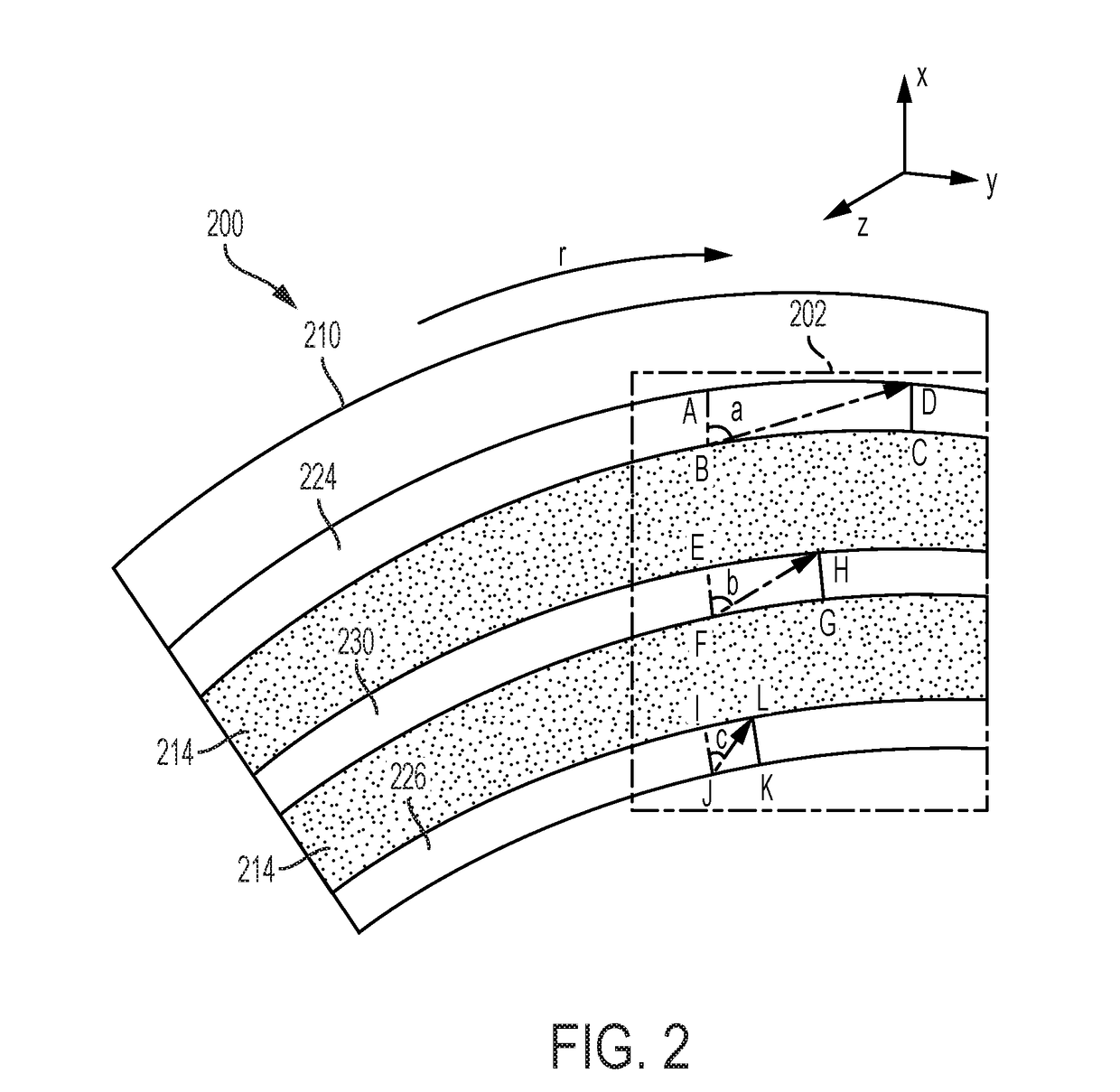
[0020]The detailed description set forth below in connection with the appended drawings is intended as a description of various configurations and is not intended to represent the only configurations in which the concepts described herein may be practiced. The detailed description includes specific details for the purpose of providing a thorough understanding of various concepts. However, it will be apparent to those skilled in the art that these concepts may be practiced without these specific details. For example, the present invention provides a preferred method for additively manufacturing certain components of metal objects, and preferably these components and these objects are used in the manufacture of jet aircraft engines. In particular, large, annular components of jet aircraft engines can be advantageously produced in accordance with this invention. However, other components of an aircraft may be prepared using the apparatuses and methods described herein.

[0021]The present...


PUM

PropertyMeasurementUnit
Angleaaaaaaaaaa
Areaaaaaaaaaaa
Dimensionaaaaaaaaaa

Abstract

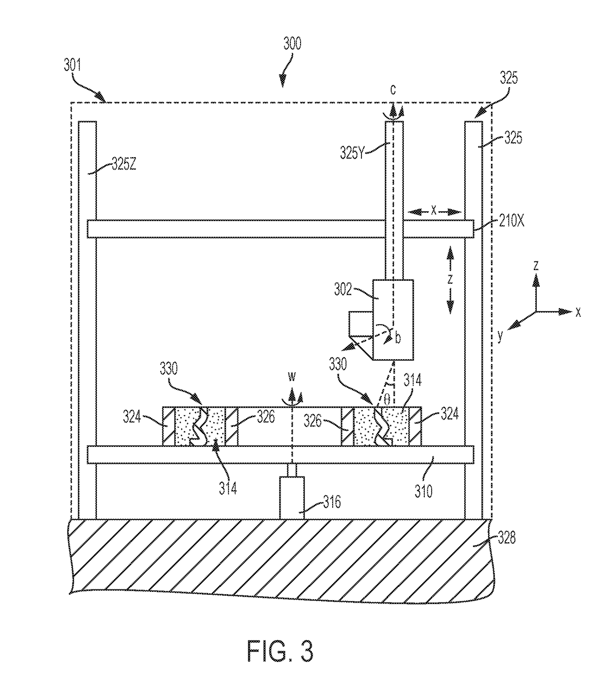
An apparatus for powder-based additive manufacturing is described. The build unit(s) of the apparatus includes a powder delivery mechanism, a powder recoating mechanism and an irradiation beam directing mechanism. The build unit is attached to a positioning mechanism that provides the build unit with independent movements in at least two dimensions. The build platform of the apparatus is rotating and preferably vertically stationary. Embodiments of the build unit that further includes a gas-flow mechanism and the build platform having a dynamically grown wall are also described. An additive manufacturing method using the apparatus involves rotating the build platform and repetitive cycles of moving the build unit(s) in a radial direction to deposit at least one layer of powder, and irradiating a selected portion of the powder to form a fused additive layer.

Description

INTRODUCTION[0001]The present disclosure generally relates to additive manufacturing apparatuses and methods. More specifically, the present disclosure relates to apparatuses and methods that enable additive manufacturing on a large-scale format or reduce the amount of powder necessary to build radial-shaped objects. These apparatuses and methods are useful but are not limited to the additive manufacturing of components of an aircraft engine.BACKGROUND[0002]Additive manufacturing (AM) encompasses a variety of technologies for producing components in an additive, layer-wise fashion. In powder bed fusion which is one of the most popular AM technologies, a focused energy beam is used to fuse powder particles together on a layer-wise basis. The energy beam may be either an electron beam or laser. Laser powder bed fusion processes are referred to in the industry by many different names, the most common of which being selective laser sintering (SLS) and selective laser melting (SLM), depe...

Claims


Application Information

Patent Timeline
IPC IPC(8): B22F3/105B33Y10/00B33Y30/00
CPCB22F3/1055B22F2003/1056B33Y30/00B33Y10/00B33Y80/00B22F5/009Y02P10/25B22F10/40B22F10/28B22F12/52B22F12/67B22F12/37
Inventor MAMRAK, JUSTINORTNER, JONATHANREDDING, MACKENZIE RYAN
Owner GENERAL ELECTRIC CO
Learn More