Suspension apparatus

a suspension and suspension technology, applied in the direction of resilient suspensions, interconnection systems, vehicle springs, etc., can solve the problems of large size of the entire system and high cos

Inactive Publication Date: 2018-12-06
KYB CORP
View PDF8 Cites 4 Cited by
  • Summary
  • Abstract
  • Description
  • Claims
  • Application Information

AI Technical Summary

Benefits of technology

[0005]Although the above-mentioned suspension apparatus can suppress the rolling of the vehicle body, the above-mentioned suspension apparatus includes four hydraulic damping mechanisms provided in the oil passages (two of which are provided in the first oil passage and the remaining two are provided in the second oil passage) and two hydraulic damping mechanisms provided in the accumulators. In other words, the above-mentioned suspension apparatus includes a total of six hydraulic damping mechanisms.
[0006]Respective hydraulic damping mechanisms are constituted by a plurality of valve groups. The conventional suspension apparatus including six hydraulic damping mechanisms requires numerous valves. Therefore, the entire system is large in size and high in cost.
[0007]The present invention intends to provide a suspension apparatus that is compact and can reduce the cost.

Problems solved by technology

Therefore, the entire system is large in size and high in cost.

Method used


Image

  • Suspension apparatus
  • Suspension apparatus

Examples


first embodiment

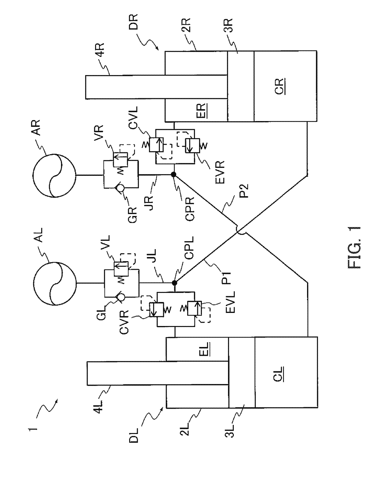
[0012]A suspension apparatus 1 according to the first embodiment, as illustrated in FIG. 1, includes a first damper DL and a second damper DR, a first flow path P1 connecting an extension-side chamber EL of the first damper DL and a contraction-side chamber CR of the second damper DR, a second flow path P2 connecting a contraction-side chamber CL of the first damper DL and an extension-side chamber ER of the second damper DR, a first accumulator AL connected to the first flow path P1, a second accumulator AR connected to the second flow path P2, a first extension-side damping valve EVL and a first contraction-side damping valve CVR provided in parallel with each other in the first flow path P1, a second extension-side damping valve EVR and a second contraction-side damping valve CVL provided in parallel with each other in the second flow path P2, a first damping valve VL and a first check valve GL provided in parallel with each other between the first flow path P1 and the first accu...

second embodiment

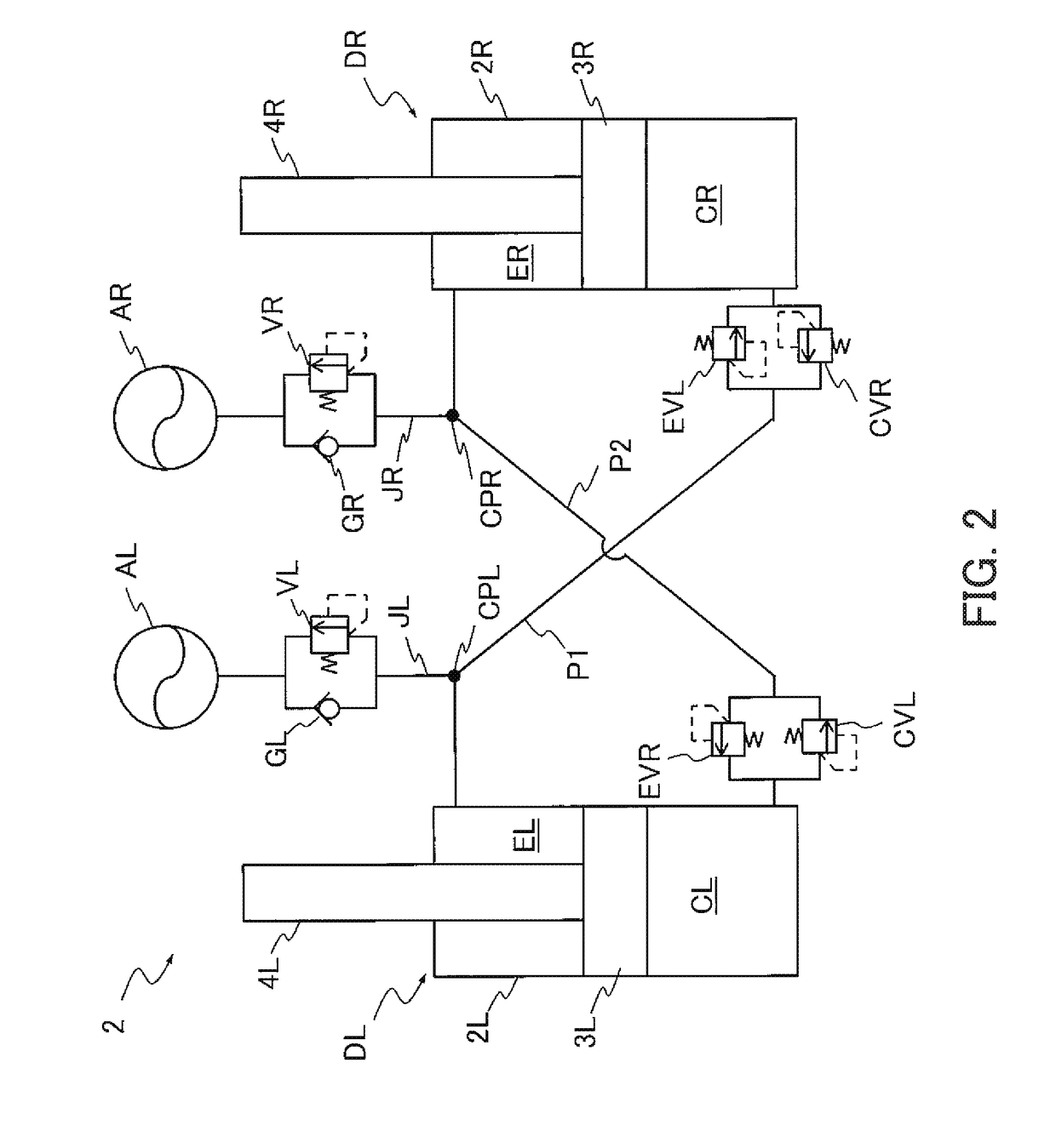
[0046]A suspension apparatus 2 according to the second embodiment, as illustrated in FIG. 2, is different from the suspension apparatus 1 according to the first embodiment in installation positions of the first extension-side damping valve EVL, the first contraction-side damping valve CVR, the second extension-side damping valve EVR, and the second contraction-side damping valve CVL.

[0047]More specifically, in the suspension apparatus 2, the first extension-side damping valve EVL and the first contraction-side damping valve CVR are provided in parallel with each other between the connecting point CPL of the first flow path P1 and the contraction-side chamber CR of the second damper DR. In addition, in the suspension apparatus 2, the second extension-side damping valve EVR and the second contraction-side damping valve CVL are provided in parallel with each other between the connecting point CPR of the second flow path P2 and the contraction-side chamber CL of the first damper DL. The...


PUM


Abstract

A suspension apparatus includes a first extension-side damping valve provided in the first flow path; a first contraction-side damping valve provided in the first flow path in parallel with the first extension-side damping valve; a second extension-side damping valve provided in the second flow path; a second contraction-side damping valve provided in the second flow path in parallel with the second extension-side damping valve; a first damping valve configured to impart resistance to the flow of fluid from the first flow path to the first accumulator; a first check valve disposed in parallel with the first damping valve; a second damping valve configured to impart resistance to the flow of fluid from the second flow path to the second accumulator; and a second check valve disposed in parallel with the second damping valve.

Description

TECHNICAL FIELD[0001]The present invention relates to a suspension apparatus.BACKGROUND ART[0002]JP2013-100058A discloses a suspension apparatus that can suppress a change in posture of a vehicle. This suspension apparatus includes a pair of hydraulic cylinders, one of which is mounted between a vehicle body and a right wheel and the other of which is mounted between the vehicle body and a left wheel, a first oil passage connecting an extension-side chamber of one hydraulic cylinder with a contraction-side chamber of the other hydraulic cylinder, a second oil passage connecting a contraction-side chamber of one hydraulic cylinder with an extension-side chamber of the other hydraulic cylinder, a first accumulator connected to the first oil passage, a second accumulator connected to the second oil passage, a first upper hydraulic damping mechanism and a first lower hydraulic damping mechanism provided in the first oil passage in such a way as to sandwich a connecting point between the...

Claims


Application Information

Patent Timeline
Patent Type & Authority Applications(United States)
IPC IPC(8): B60G21/073B60G21/02
CPCB60G21/073B60G21/026B60G2202/24B60G2500/11B60G2800/012B60G11/30B60G2204/8304B60G2204/82B60G13/08B60G17/0162
Inventor CHIKAMATSU, SATOSHIKAWAKAMI, HIDEKI
Owner KYB CORP
Why Eureka
Try Eureka