Cargo Transfer Vessel

a cargo transfer and cargo technology, applied in the direction of vessel construction, passenger handling apparatus, vessel movement reduction by foils, etc., can solve the problems of limited maneuverability and station keeping capabilities of tankers with calm buoys, difficulty in ensuring safety, and difficulty in loading fluid to tankers in open sea. , to achieve the effect of reducing the propulsion resistance of the vessel

Active Publication Date: 2017-11-30
SEALOADING HLDG AS
View PDF7 Cites 2 Cited by
  • Summary
  • Abstract
  • Description
  • Claims
  • Application Information

AI Technical Summary

Benefits of technology

This invention is about a ship that can transfer fluids between an offshore oil production facility and a tanker. The ship has a unique design that keeps it stable during fluid transfer operations. It has a hull with extra parts that stick out from the sides and actively move to keep the ship at a specific distance from the oil production facility and the tanker. This design also reduces the resistance to the ship's propulsion.

Problems solved by technology

Loading of fluid to tankers in open sea may be a demanding operation, in particular in harsh environment.
The operation requires dedicated shuttle tankers equipped with dynamic positioning system, excessive thruster capacity and specialized loading systems.
Loading of tankers with CALM buoys are limited by the sea state, current and wind.
The main challenge using conventional tankers are their limited maneuvering and station keeping capabilities.
However, the disclosed system is considered vulnerable to environmental induced movements such as roll, in particular during liquid transfer.
In addition, the suitability for use as an effective means of transport is questionable.

Method used


Image

  • Cargo Transfer Vessel
  • Cargo Transfer Vessel
  • Cargo Transfer Vessel

Examples


Embodiment Construction

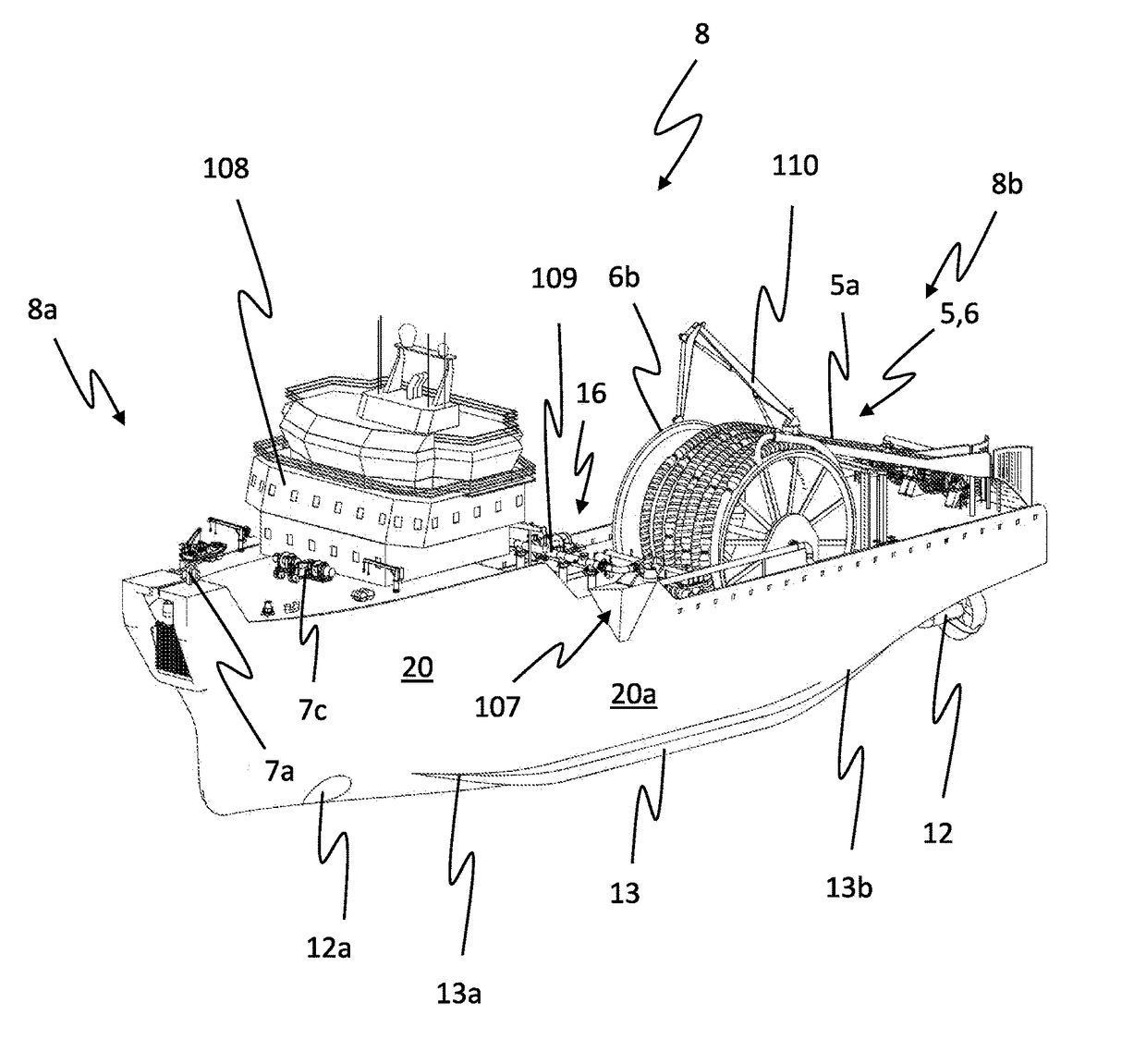
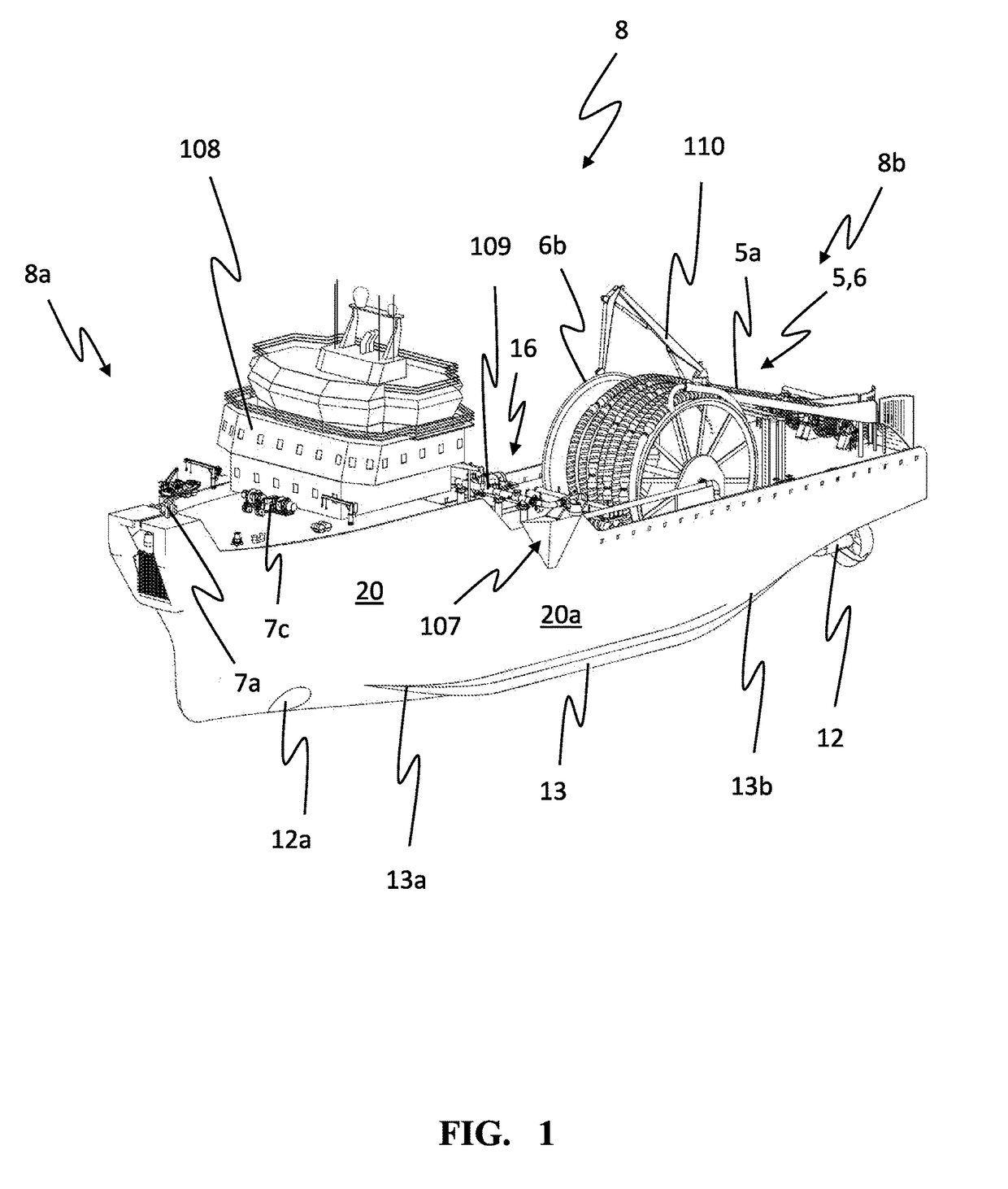
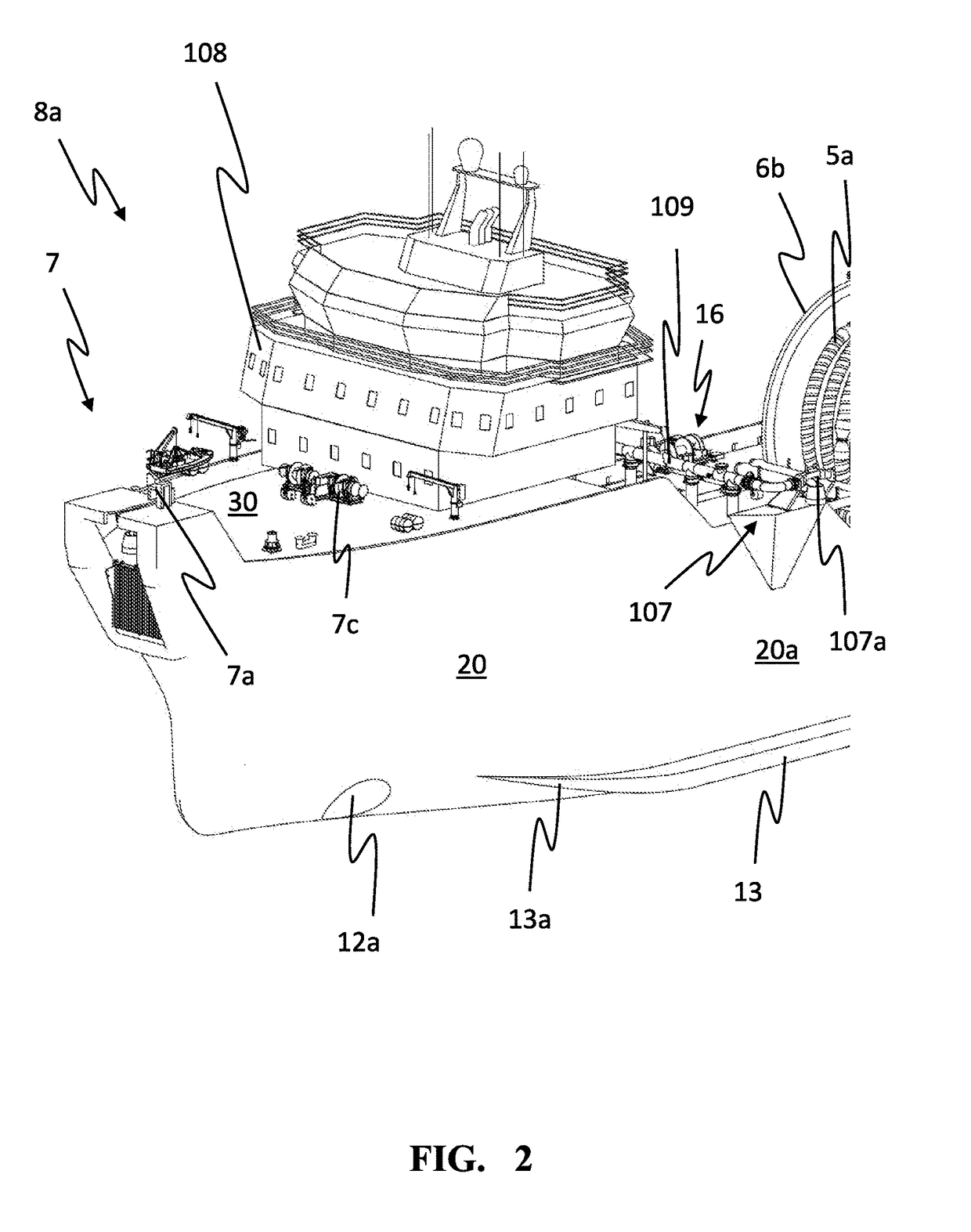
[0062]FIGS. 1 and 2 shows a cargo transfer vessel 8 in accordance with the invention, hereinafter referred to as a CTV, for assisting the offloading and transfer of fluid from an offshore production facility 1 to a fluid carrying vessel 2 (shown in FIGS. 12-18). Examples of offshore production facilities 1 may be a floating production storage and offloading unit (FPSO), a floating storage and offloading unit (FSO) or a floating liquefied natural gas unit (FLNG). Examples of fluid carrying vessels 2 may be a conventional tanker or a LNG carrier. As best illustrated in FIG. 2 the bow part 8a of the CTV 8 is equipped with a loading arrangement 7 having a loading manifold 7a configured to connect an end of a production facility loading hose 10 (such as a standard dry break loading hose end piece) into fluid communication with an onboard fluid coupling system 16. The loading arrangement 7 also includes a loading crane (not shown) to inter alia facilitate said connection. The loading mani...


PUM


Abstract

The invention concerns a cargo transfer vessel for transferring fluid between an offshore production facility and a tanker and a method for transferring the fluid. The cargo transfer vessel comprise a hull having a first and a second outer longitudinal hull side; a deck, propulsion means for actively maintaining the cargo transfer vessel at a predetermined distance from the offshore production facility and the tanker during fluid transfer operations and fluid transfer means for transferring fluid between the offshore structure and the tanker. The vessel is further characterized in that the hull comprises a main hull member and at least one protruding hull member arranged below the cargo transfer vessels water line at each of the outer longitudinal hull sides for suppressing roll of the vessel, wherein the at least one protruding hull member extends at least partly along the hulls longitudinal length, i.e. from the start of the vessel's bow to the end of the vessel's aft.

Description

CROSS REFERENCE TO RELATED APPLICATIONS[0001]This a continuation application under 35 U.S.C. §120 of application 14 / 898,751 filed 16 Dec., 2015, which is a National Stage application of PCT / EP2014 / 063141 filed 23 Jun., 2014.TECHNICAL FIELD[0002]The invention concerns a method and a system for transferring hydrocarbon fluid from an offshore production facility to a fluid carrying vessel.BACKGROUND AND PRIOR ART[0003]Loading of fluid to tankers in open sea may be a demanding operation, in particular in harsh environment. The operation requires dedicated shuttle tankers equipped with dynamic positioning system, excessive thruster capacity and specialized loading systems. Such shuttle tankers are equipped with loading systems, normally installed in the vessel's bow, enabling the tanker to connect to a floating production facility, a loading tower or loading buoy via a loading hose, and thereby allowing transfer of the cargo to the tanker. The tanker can be moored to the production by a ...

Claims


Application Information

Patent Timeline
Patent Type & Authority Applications(United States)
IPC IPC(8): B63B27/25B63B1/32B63B35/66B63B27/34B63B35/44B63B39/06
CPCB63B35/66B63B27/25B63B1/32B63B2039/067B63B2035/448B63B27/34B63B39/06
Inventor SYVERTSEN, KARESMEDAL, ARNE
Owner SEALOADING HLDG AS
Why Eureka
Try Eureka