Disk drive having mechanism for preventing tray from rolling

a technology of preventing the roll of the tray and a mechanism, which is applied in the direction of information storage, instruments, data recording, etc., can solve the problems of unstable disk exchanging position, limited space on the lower side of the tray, and inability to adjust the position of the disk, so as to prevent the generation of warp, and ensure the effect of smooth operation

Inactive Publication Date: 2006-06-01
ORION ELECTRIC CO LTD
View PDF15 Cites 3 Cited by
  • Summary
  • Abstract
  • Description
  • Claims
  • Application Information

AI Technical Summary

Benefits of technology

[0013] Only the longitudinal cam groove of the first cam groove may be composed of only one rib. Even in the process of carrying out the tray along the longitudinal cam groove, the tray is supported by the guide rails provided on the chassis. Therefore, the tray can be smoothly carried out without rolling.
[0014] As described above, on the tray of the disk drive of the present invention, the rack is provided on one side of the bottom face, the substantially L-shaped first cam groove is provided on the opposite side, and the second cam groove is provided at the rear end portion in the neighborhood of the rack in such a manner that the positions of the rack, the first cam groove and the second cam groove are well balanced. Accordingly, the mechanical strength of the entire tray is made uniform, and it is possible to prevent the generation of warp. Therefore, the tray can b

Problems solved by technology

However, the tray 1 located at the disk exchanging position is not stable because only the rear end portion of the tray 1 is supported by the guide rails.
However, since the engagement groov

Method used


Image

  • Disk drive having mechanism for preventing tray from rolling
  • Disk drive having mechanism for preventing tray from rolling
  • Disk drive having mechanism for preventing tray from rolling

Examples


Embodiment Construction

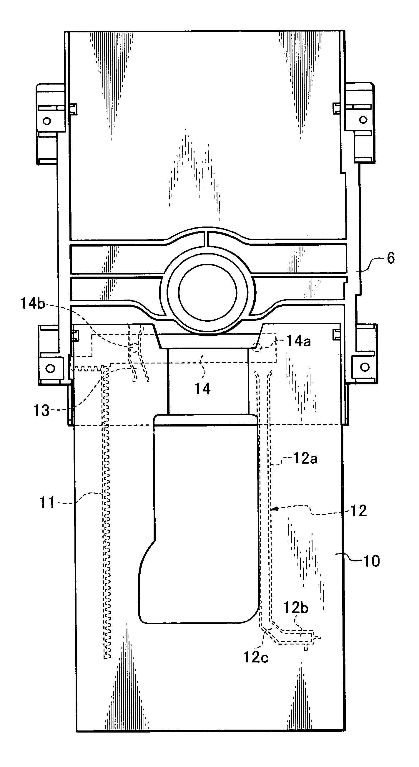
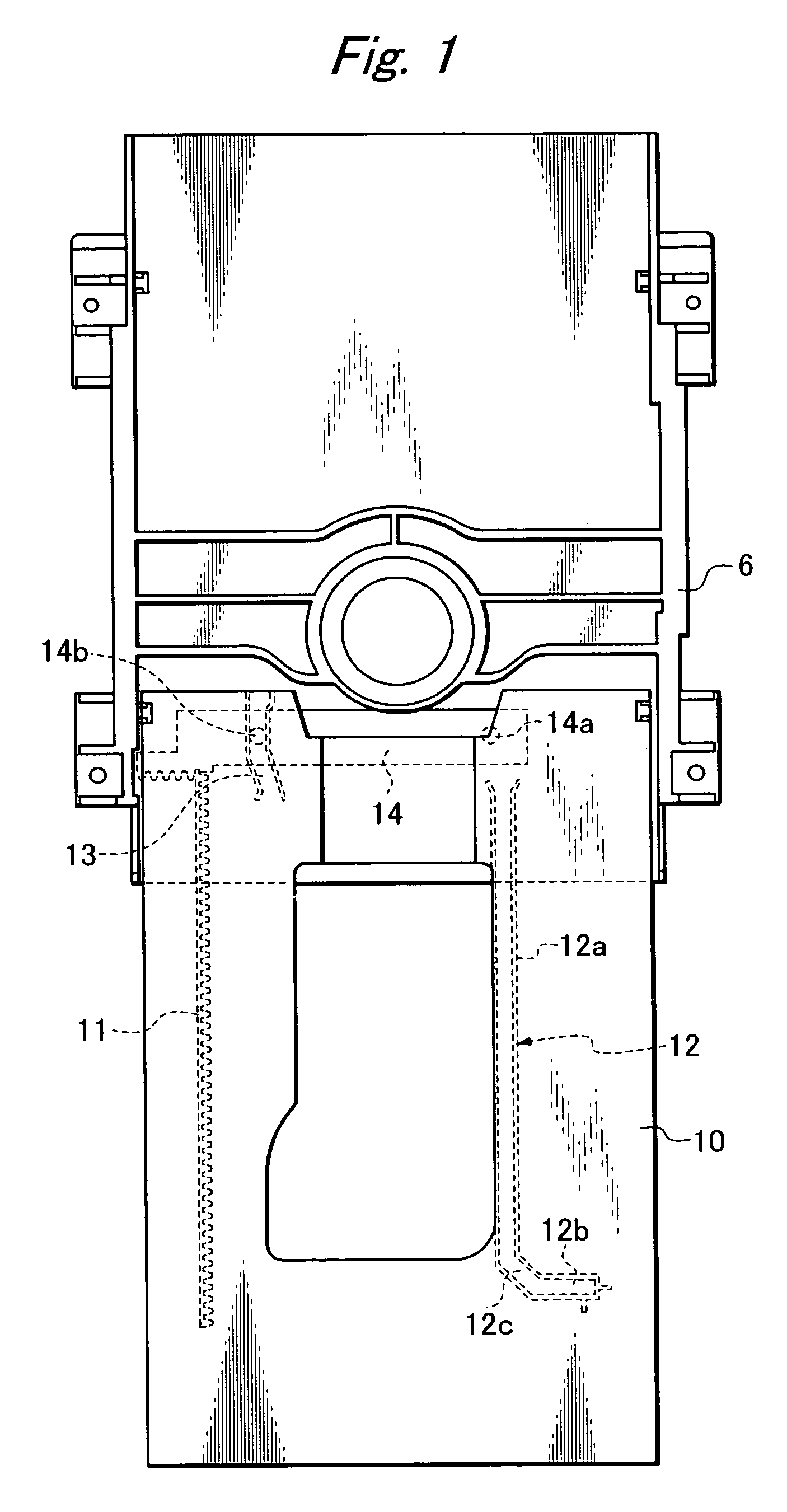
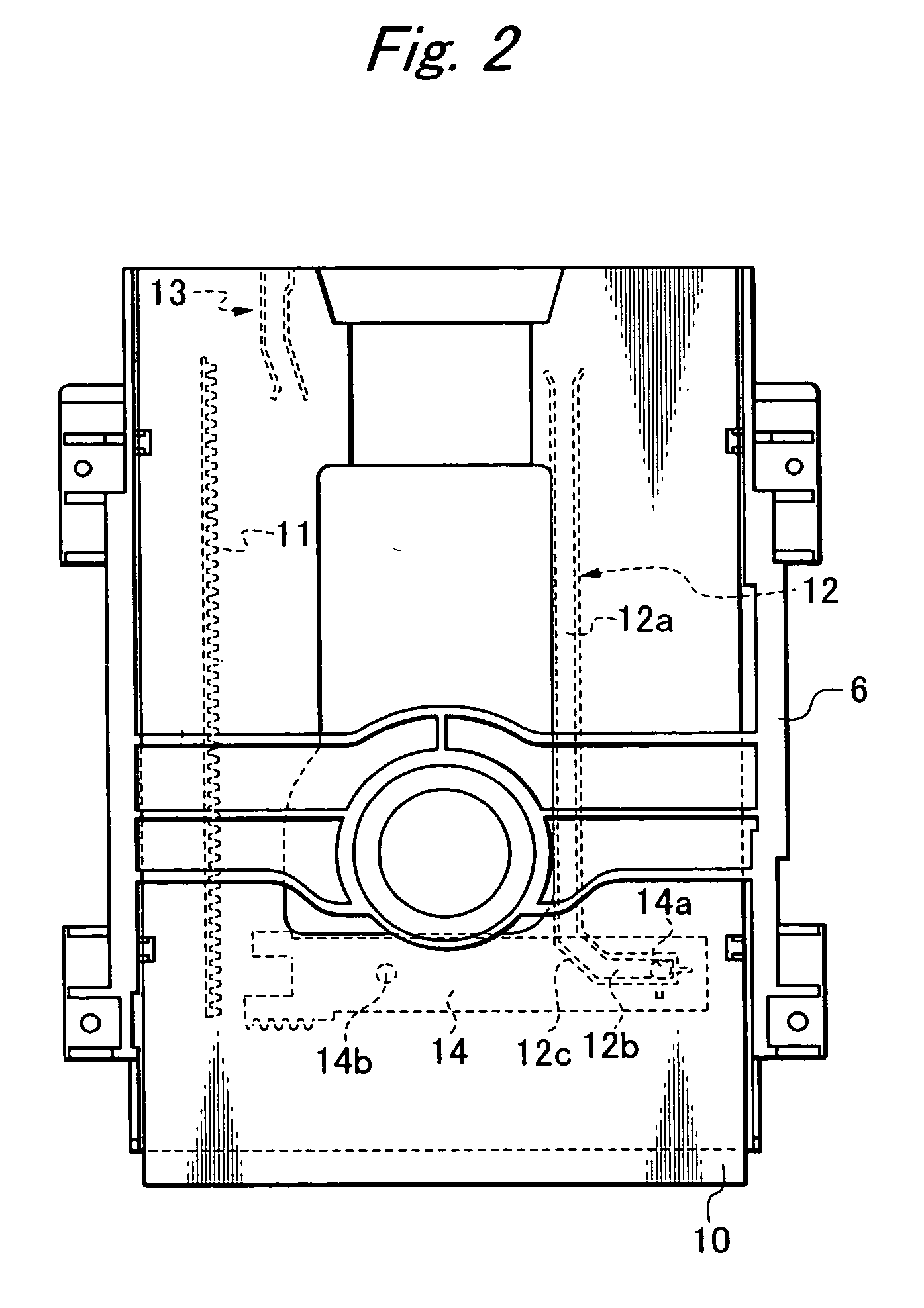
[0026] FIGS. 1 to 5B show a disk drive of the first embodiment of the present invention. Portions of this disk drive except for a tray 10 and a rack loading 14 are essentially the same as those of the related art shown in FIG. 8. Therefore, identical reference numerals are used to indicate the identical parts in these drawings, and the detail explanations on the drawings are omitted here. As shown in FIGS. 1 and 2, a rack 11 extending in the longitudinal direction is provided on one side on the lower face of the tray 10. On the other side on the lower face of the tray 10, a substantially L-shaped first cam groove 12 is provided. In the neighborhood at the rear of the rack 11, a second cam groove 13 is provided. The rack 11, the first cam groove 12 and the second cam groove 13 are formed of synthetic resin by means of integral molding. The first cam groove 12 includes: a longitudinal cam groove 12a extending in parallel with the rack 11; a lateral cam groove 12b arranged perpendicula...


PUM


Abstract

In order to suppress a tray from rolling and to prevent the tray from warping so as to reduce the thickness of a disk drive, the tray is provided on the lower face thereof a substantially L-shaped first cam groove formed on the opposite side to the rack side, and a curved second cam groove formed at a rear end portion of the tray in the neighborhood of the rack; and a rack loading is provided with a first cam rod boss protruding therefrom and slidably engaging with the first cam groove, and a second cam rod boss protruding therefrom and slidably engaging with the second cam groove; so that the entire tray can be well balanced and the mechanical strength can be made uniform in the disk drive.

Description

BACKGROUND OF THE INVENTION [0001] 1. Field of the Invention [0002] The present invention relates to a disk drive having a function of preventing a tray from rolling in an open state in which the tray is carried to a disk exchanging position. [0003] 2. Related Art [0004] In a disk drive having a tray capable of freely reciprocating between a disk exchanging position and a disk reproducing position, the tray is reciprocated in the longitudinal direction being supported by guide rails provided on a chassis. As shown in FIG. 8, a pinion 4 driven and rotated by a motor 5 is meshed with a rack 2 extended in the longitudinal direction on one side of the lower face of a tray 1. When the pinion 4 is rotated, the rack 2 and the tray 1 are reciprocated in the longitudinal direction. [0005] On the other side of the lower face of the tray 1, a cam groove 3, the shape of which is substantially L-shaped, is provided. A cam rod boss 7a, which protrudes from a rack loading 7 being capable of freely...

Claims


Application Information

Patent Timeline
IPC IPC(8): G11B17/04G11B17/03G11B33/02
CPCG11B17/056
Inventor NISHIDE, MASAHIKOMAKINO, TAKESHI
Owner ORION ELECTRIC CO LTD
Why Eureka
Try Eureka