Control system for variable damping force damper

a control system and damping force technology, applied in the direction of shock absorbers, mechanical equipment, transportation and packaging, etc., can solve the problem that the effect of increasing the damping force of the roll is not effective in suppressing the roll vibration, and achieves the effect of suppressing the rolling of the vehicle body and the effective effect of rolling

Active Publication Date: 2020-05-07
HONDA MOTOR CO LTD
View PDF0 Cites 1 Cited by
  • Summary
  • Abstract
  • Description
  • Claims
  • Application Information

AI Technical Summary

Benefits of technology

[0007]In view of such background, a primary object of the present invention is to provide a control system for a variable damping force damper that can suppress the rolling of the vehicle body more effectively.
[0009]Thus, by correcting the roll damping force base value based on the roll rate difference and using the corrected roll damping force base value as the target damping force of the variable damping force damper, the rolling of the vehicle body can be suppressed more effectively than when such correction is not made.
[0011]Thereby, the roll rate difference between the sprung mass roll rate and the unsprung mass roll rate can be computed properly.
[0013]Thereby, in a situation where the absolute value of the unsprung mass roll rate is large, a damping force exceeding (in absolute value) the damping force corresponding to the critical damping of the sprung mass is generated to advance the phase of the unsprung mass roll rate so that the ground contact load distribution between the left and right wheels (tires) is changed quickly. In addition, in a situation where the absolute value of the unsprung mass roll rate is small, a damping force smaller in absolute value than the damping force corresponding to the critical damping of the sprung mass is generated to advance the phase of the sprung mass roll rate so that the phase difference between the sprung mass roll rate and the unsprung mass roll rate is reduced, which suppresses an increase in the delay of the roll response.
[0015]This arrangement also can suppress the rolling of the vehicle body more effectively than a conventional arrangement that is not equipped with the above-mentioned roll damping force correction unit.
[0016]Thus, according to an embodiment of the present invention, it is possible to provide a control system for a variable damping force damper that can suppress the rolling of the vehicle body more effectively.

Problems solved by technology

If the roll damping ratio becomes one or higher, a further increase in the roll damping force is not effective in suppressing the roll vibration.

Method used


Image

  • Control system for variable damping force damper
  • Control system for variable damping force damper
  • Control system for variable damping force damper

Examples


Embodiment Construction

)

[0031]In the following, an embodiment of the present invention will be described in detail with reference to the drawings.

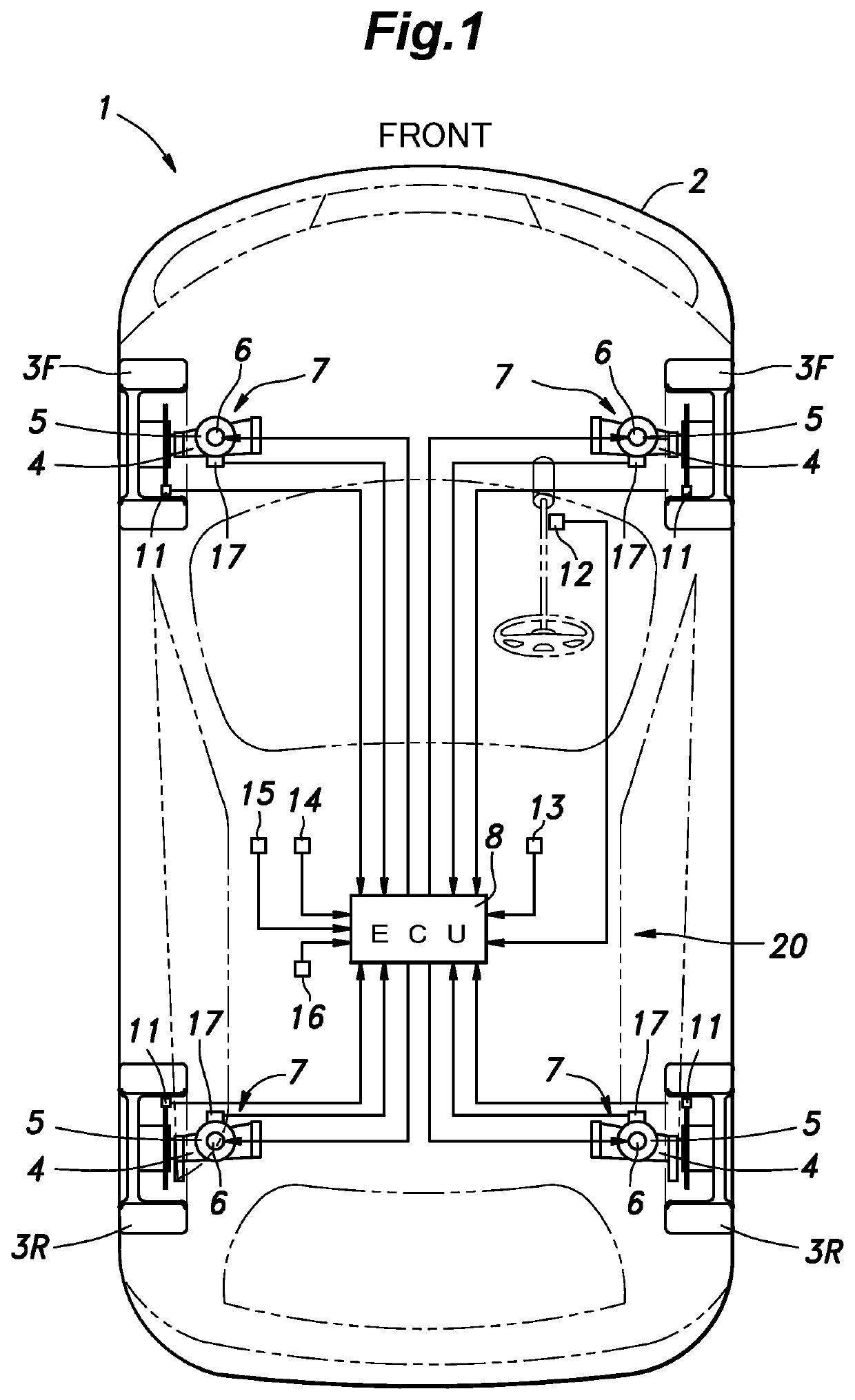
[0032]FIG. 1 is a schematic configuration diagram of a vehicle 1 provided with a control system 20 for a variable damping force damper according to an embodiment of the present invention. As shown in FIG. 1, the vehicle 1 according to the embodiment is a four-wheeled automobile having left and right wheels 3 (front wheels 3F and rear wheels 3R) installed in a front part and a rear part of a vehicle body 2. The vehicle 1 also has a power source (power plant) for driving the wheels 3 mounted thereon. Each wheel 3 is supported by the vehicle body 2 via a suspension 7 constituted of a suspension arm 4, a spring 5, a variable damping force damper 6 (hereinafter simply referred to as a damper 6), and the like. The power source of the vehicle 1 may include at least one of an internal combustion engine (such as a gasoline engine or a diesel engine) and an electric motor...


PUM


Abstract

A control system for a variable damping force damper, includes: motion state quantity sensors configured to detect motion state quantities of a vehicle; a roll damping force base value setting unit configured to set a roll damping force base value based on the motion state quantities, the roll damping force base value being used to compute a target damping force of the variable damping force damper; a roll rate computation unit configured to compute a sprung mass roll rate and an unsprung mass roll rate of the vehicle based on the motion state quantities; and a roll damping force correction unit configured to correct the roll damping force base value based on a roll rate difference that is a difference between the sprung mass roll rate and the unsprung mass roll rate and to output the corrected roll damping force base value as the target damping force.

Description

TECHNICAL FIELD[0001]The present invention relates to a control system for a variable damping force damper for controlling the roll attitude based on a motion state quantity.BACKGROUND ART[0002]In recent years, various types of variable damping force dampers, which can vary the damping force in steps or continuously, have been developed for use in suspensions of automobiles. Known mechanisms for varying the damping force include a mechanical type in which the area of an orifice provided in the piston of the damper is varied by a rotary valve and an magnet-rheological fluid (MRF) type in which MRF is used as hydraulic oil and the viscosity of the MRF is controlled by a magnetic fluid valve provided in the piston. In a vehicle equipped with such variable damping force dampers (may be simply referred to as dampers), by variably controlling the damping force of each damper depending on the running state of the vehicle, it is possible to improve the steering stability and the ride comfor...

Claims


Application Information

Patent Timeline
Patent Type & Authority Applications(United States)
IPC IPC(8): B60G17/016F16F9/50
CPCF16F9/50B60G2800/012B60G17/0162B60G2800/912B60G2400/0521B60G2500/10B60G2600/182B60G17/06B60G17/0157B60G17/01908B60G17/01933B60G17/08
Inventor GOTO, YUYAKANDA, RYOMA
Owner HONDA MOTOR CO LTD
Why Eureka
Try Eureka