Utility vehicle

a technology for utility vehicles and motors, applied in the field of utility vehicles, can solve the problems of troublesome attachment work, difficulty in coupling torque rods to an appropriate position of engines, etc., and achieve the effect of improving the vibration suppression effect on engine rolling, facilitating dynamically reasonable coupling, and improving the vibration absorption effect on engine rolling

Active Publication Date: 2016-06-30
KAWASAKI MOTORS LTD
View PDF0 Cites 2 Cited by
  • Summary
  • Abstract
  • Description
  • Claims
  • Application Information

AI Technical Summary

Benefits of technology

[0009](a) The engine includes an engine cooling fan at an end in the vehicle width direction, the engine cooling fan is located at an extending side of the torque rod, and the torque rod extends over the engine cooling fan. This configuration achieves location of the torque rod and the cooling fan with no interference therebetween.
[0010](b) The torque rod has each end in an extending direction provided with a pillow ball joint. This configuration facilitates dynamically reasonable coupling of the respective ends of the torque rod to desired positions. This configuration also releases an excess load applied to the torque rod.
[0011](c) The torque rod has one end in an extending direction provided with a pillow ball joint and other end provided with a rubber damper joint. This configuration improves a vibration absorption effect on rolling of the engine.
[0012](d) The engine has each end in a front-rear direction of the vehicle supported by a cross member extending in the vehicle width direction of the chassis frame. This configuration improves a vibration suppression effect on rolling of the engine.
[0013](e) The torque rod bracket is an engine hanger having an engagement portion configured to suspend the engine. This configuration achieves sharing of components to reduce the number of components.
[0014](f) The torque rod extends in the vehicle width direction and has ends in an extending direction coupled to the frame member at one end in the vehicle width direction and a frame member provided at the other end. This configuration improves the vibration suppression effect on rolling of the engine, and also enhances rigidity of the chassis frame supporting the engine.

Problems solved by technology

The torque rod may be thus occasionally difficult to be coupled to an appropriate position of the engine.
The torque rod also requires troublesome attaching work.

Method used


Image

  • Utility vehicle
  • Utility vehicle
  • Utility vehicle

Examples


Embodiment Construction

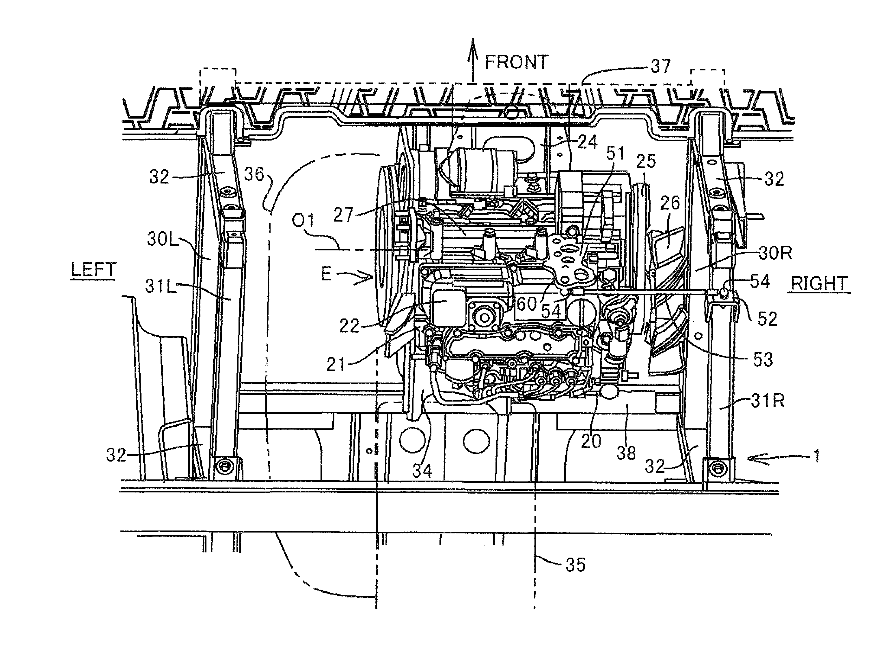
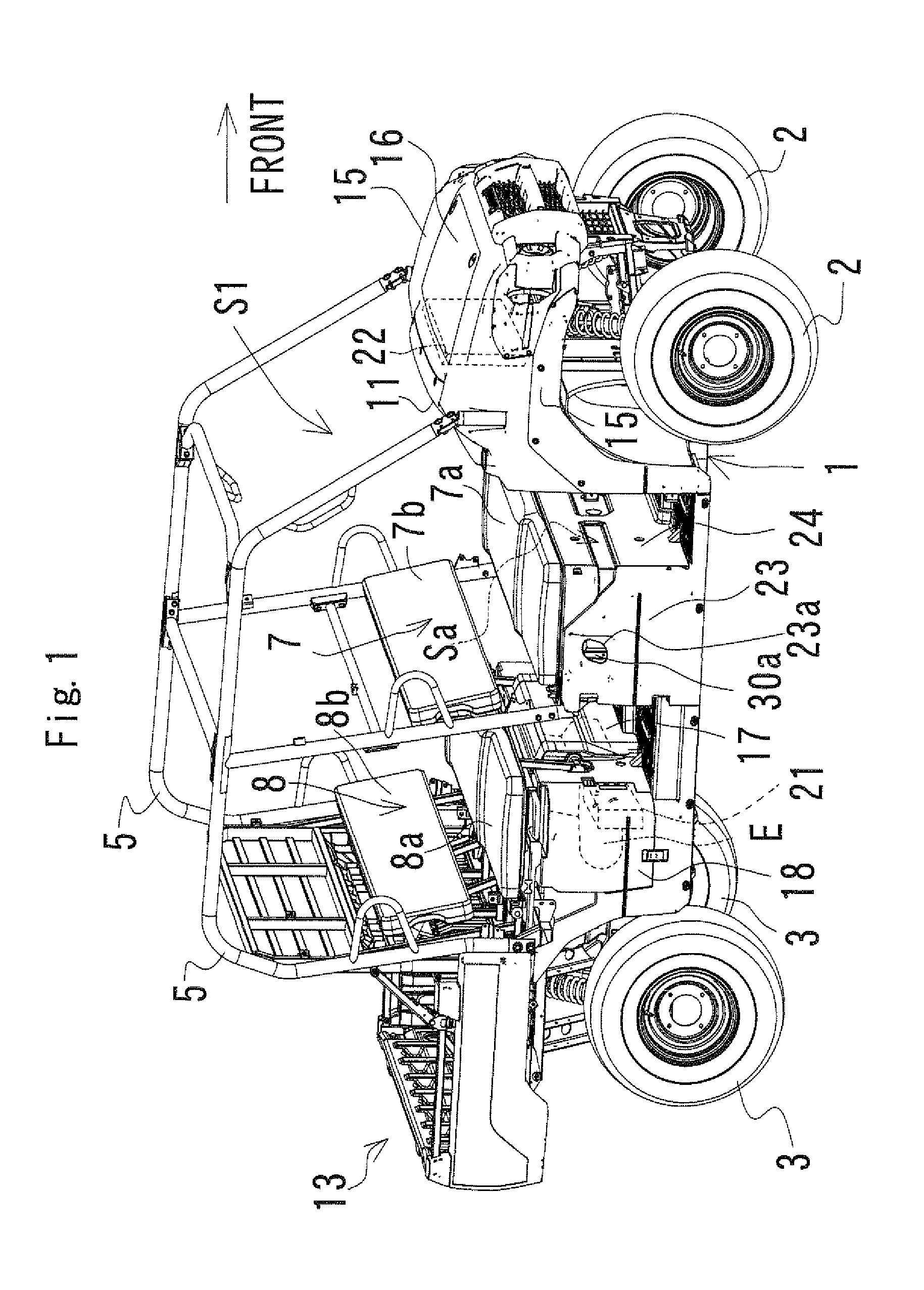
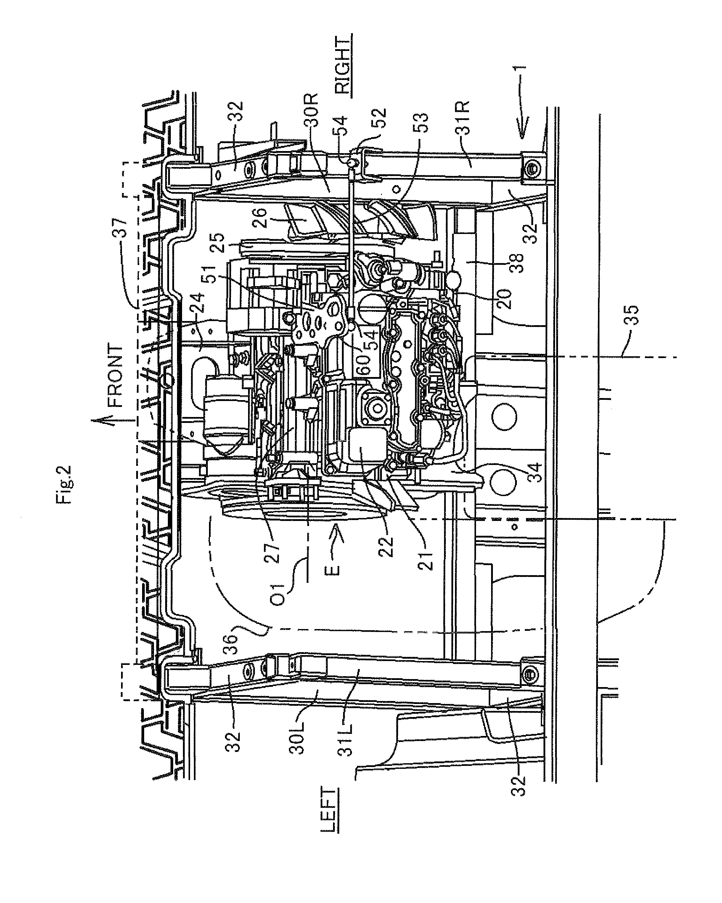
[0024]FIGS. 1 to 6 show a utility vehicle according to the present invention. A preferred embodiment of the present invention will now be described with reference to these figures. For convenience of description in this embodiment, a forward travelling direction of the vehicle is called “front” of the vehicle and each of components of the vehicle, and a right and left direction as seen from a driver or passenger is called “a right and left direction” of the vehicle and each of the components of the vehicle.

[0025]FIG. 1 is a perspective view of the entire utility vehicle. The utility vehicle includes a chassis frame 1, right and left front wheels 2 located at a front end of the chassis frame 1, and right and left rear wheels 3 located at a rear end of the chassis frame 1. A cabin (riding space) S1 is located between the front wheels 2 and the rear wheels 3 in a front-rear direction, and is surrounded with a R.O.P.S. 5. The cabin S1 accommodates a bench type front sheet 7 and a bench ...


PUM


Abstract

A utility vehicle includes: a chassis frame, a cargo bed, a cabin, and an engine. The utility vehicle further includes: a torque rod bracket fixed to an engine body forming a shell or outline of the engine and projecting upward from an upper end of the engine body; and a torque rod provided at a position higher than the upper end of the engine body and coupling the torque rod bracket and a frame member provided at one end in a vehicle width direction of the engine.

Description

BACKGROUND OF THE INVENTION[0001]1. Field of the Invention[0002]The present invention relates to a utility vehicle, and particularly to a mounting structure for an engine mounted to the utility vehicle.[0003]2. Description of the Prior Art[0004]U.S. Pat. No. 8,727,063 discloses a utility vehicle that includes an engine supported by a chassis frame at two positions in a front-rear direction of the vehicle. The utility vehicle further includes a torque rod that is bridged between an engine body and a frame member provided at an end in a vehicle width direction to suppress rolling of the engine in the vehicle width direction.[0005]The torque rod of the utility vehicle described in U.S. Pat. No. 8,727,063 couples the lower half (crankcase) of the engine body and the frame member at an end in the vehicle width direction. The torque rod coupled to the lower half of the engine body has less flexibility in location of the torque rod because the torque rod needs to be located so as not to in...

Claims


Application Information

Patent Timeline
Patent Type & Authority Applications(United States)
IPC IPC(8): B60K5/12B60K11/06
CPCB60K11/06B60K5/1208B60K5/1241B60Y2200/124B60Y2200/23
Inventor OHSHITA, YUJINOZAKI, TAKUMANAKATANI, HIROSHI
Owner KAWASAKI MOTORS LTD
Why Eureka
Try Eureka