

LED headlamp projection lighting device
- Summary
- Abstract
- Description
- Claims
- Application Information
AI Technical Summary
Benefits of technology
Problems solved by technology
Method used
Image

Examples
first embodiment
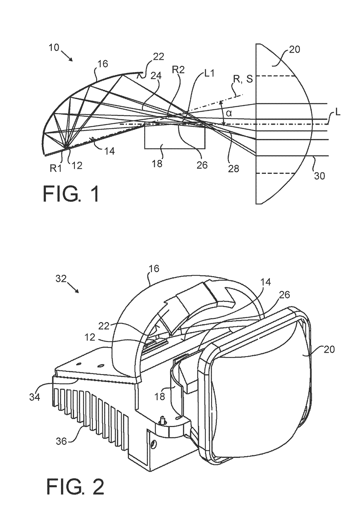
[0024]FIG. 1 schematically shows a central longitudinal sectional view of a lighting device 10 according to a An LED light source 12 is arranged on a flat surface 14 covered by a half dome shaped reflector 16.
[0025]A projection lens 20 is arranged in front of the reflector 16. A shield 18 is arranged between the reflector 16 and the projection lens 20.
[0026]The reflector 16 has a first focus R1 and a second focal region R2. An inner reflector surface 22 of the reflector 16 is shaped such that light emitted from the first reflector focus R1 is reflected to the second focal region R2.
[0027]The LED light source 12 is arranged within the first reflector focus R1. The shield 18 is arranged within the second focal region R2 of the reflector 16. A reflector axis R may be defined through the first reflector focus R1 and a portion of the focal region R2. The projection lens 20 has a first lens focus L1, defining an optical axis L through the first lens focus L1 and a center of the lens 20. ...
second embodiment
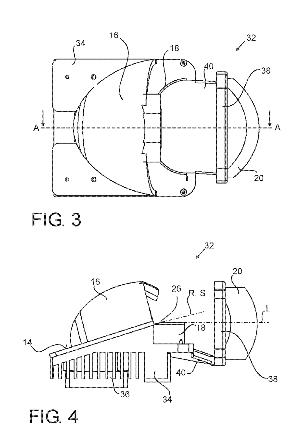
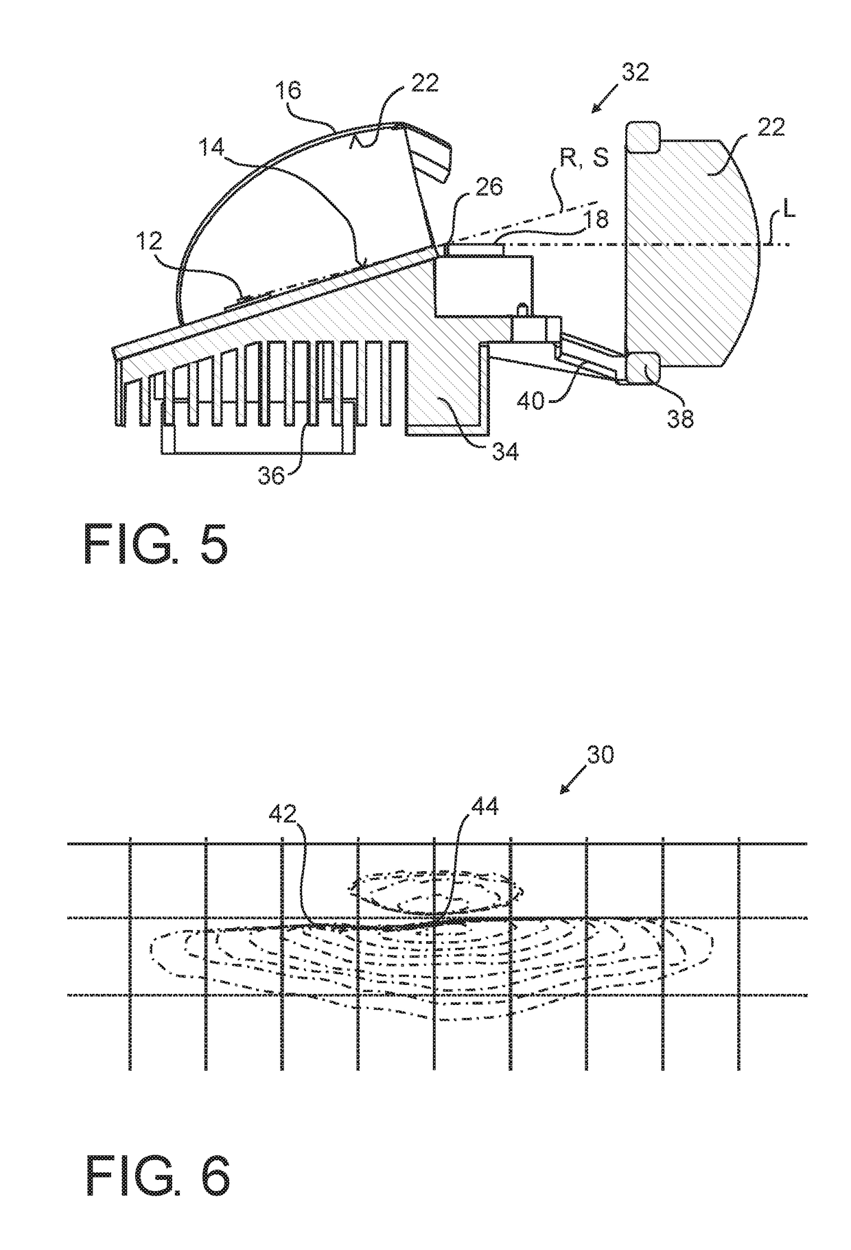
[0034]FIGS. 2-5 show a vehicle headlight 32 according to a The vehicle headlight 32 is a more specific embodiment, yet comprises the same basic elements as the lighting device of FIG. 1. In the following, only differences between the embodiments will be further explained. Like reference numerals will be used to refer to like parts.
[0035]In the vehicle headlight 32, a heat sink 34 body including cooling fins 36 forms a base of the device. All elements are fixed to the head sink body 34.
[0036]The inclined surface 14 is formed on top of the heat sink body 34 and the reflector 16 is mounted on the inclined surface 14. The shield 18 is fixed to a front side of the heat sink body 34. The projection lamp 22 is held in a frame 38 arranged by a holding arm 40 extending from the heat sink body 34.
[0037]The optical arrangement of the main components of the vehicle headlight 32, namely the LED light source 12, reflector 16, shield 26 and projection lens 20 is as already explained with regard t...
PUM
 Abstract
Description
Claims
Application Information