Reflective transparent screen and image projection device comprising same

Active Publication Date: 2018-12-06
ENEOS CORP
View PDF4 Cites 9 Cited by
  • Summary
  • Abstract
  • Description
  • Claims
  • Application Information

AI Technical Summary

Benefits of technology

[0029]According to the present invention, a reflective transparent screen can be provided, satisfying both visibilities of the projection light and the transmitted light by anisotropical diffuse reflection of the projection

Problems solved by technology

However, since a conventional projector screen is low in transparency, there is a technical p

Method used


Image

  • Reflective transparent screen and image projection device comprising same
  • Reflective transparent screen and image projection device comprising same
  • Reflective transparent screen and image projection device comprising same

Examples


Example

Example 1

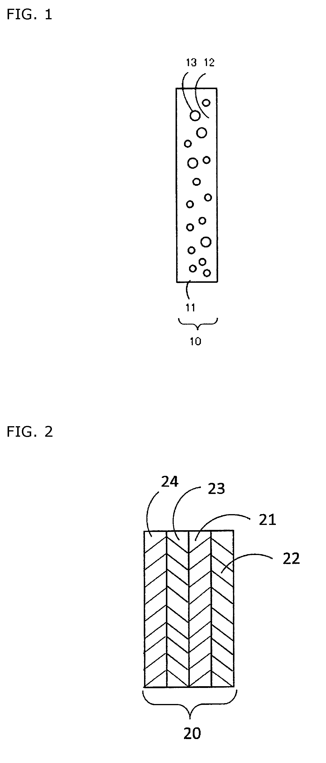
[0119]A polyethylene terephthalate (PET) pellet (manufactured by Bell Polyester Products, Inc., brand name: IFG8L) and 0.012% by mass of flake form aluminum microparticles A (light reflective microparticles, primary particles with average diameter: 1 μm, aspect ratio: 300, regular reflectance: 62.8%) based on the PET pellet were mixed for 30 minutes in a tumbler mixer to obtain a PET pellet which flake form aluminum was attached to its surface homogeneously. The obtained pellet was supplied to a hopper of a twin-screw kneading extruder with a strand die and a masterbatch in which flake form aluminum are kneaded in was obtained at an extrusion temperature of 250° C. The obtained masterbatch and the PET pellet (brand name: IFG8L) were mixed homogeneously in a proportion of 1:2, introduced into a hopper of a single-screw extruder with a T die, and extruded at extrusion temperature of 250° C. to produce a film in a thickness of 75 μm. Since the flake form aluminum microparticle...

Example

Example 2

[0122]A transparent screen was obtained by attaching a commercially available low reflective film (Realook 2702 UV / NP-50, manufactured by NOF Corporation) to the film (light diffusion layer) side of the transparent screen obtained in Example 1.

[0123]The obtained transparent screen had a total light transmittance of 90.2%, a parallel beam transmittance of 85.9%, a luminous reflectance Y of 2.5%, and an image clarity of 96%.

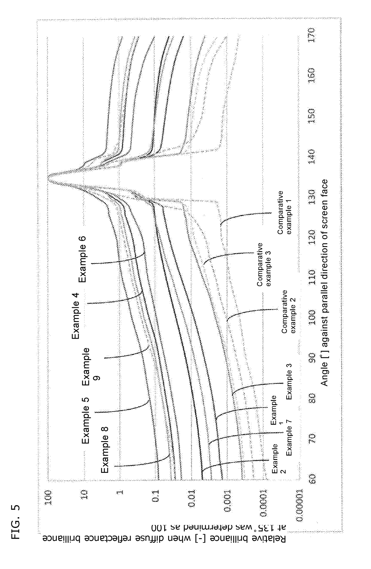
[0124]When the diffuse reflectance light brilliance profile of the transparent screen was measured with a goniophotometer, the relative brilliance of the diffuse reflectance light at 60 degrees was 0.005, at 90 degrees was 0.014, and at 120 degrees was 0.083, when light was entered at an angle of 45 degrees against the parallel direction of the screen face and the brilliance of diffuse reflectance light in the specular reflection direction (135 degrees) was determined as 100. This diffuse reflectance light brilliance profile is shown in FIG. 5. When an ima...

Example

Example 3

[0125]A PET pellet (manufactured by Bell Polyester Products, Inc., brand name: IFG8L) and 0.005% by mass of flake form aluminum microparticles A based on the PET pellet were mixed for 30 minutes in a tumbler mixer to obtain a PET pellet which flake form aluminum was attached to its surface homogeneously. The obtained pellet was supplied to a hopper of a twin-screw kneading extruder with a strand die, extruded at extrusion temperature of 250° C. to obtain a masterbatch in which flake form aluminum are kneaded in. The obtained masterbatch and the PET pellet (brand name: IFG8L) were mixed homogeneously in a proportion of 1:4, introduced into a hopper of a single-screw extruder with a T die, and extruded at extrusion temperature of 250° C. to produce a film in a thickness of 50 μm. Since the flake form aluminum microparticles concentration in the film was 0.001% by mass, the film (light diffusion layer) thickness t (μm) and the concentration c (% by mass) of the flake form alum...


PUM


Abstract

A reflective transparent screen according to the present invention comprises a light diffusion layer which comprises a binder and microparticles. The reflective transparent screen has a total light transmission of 60% or more and a parallel beam transmittance of 50% or more. The transparent screen has the diffuse reflectance light brilliance profile measured with a goniophotometer characterized to satisfy the conditions A and B.

Description

TECHNICAL FIELD[0001]The present invention relates to a reflective transparent screen satisfying both visibilities of projection light and transmitted light by anisotropical diffuse reflection of projection light emitted from a light source. The present invention also relates to an image projection device comprising the reflective transparent screen and a projection device.BACKGROUND ART[0002]Conventionally, a combination of a Fresnel lens sheet and a lenticular lens sheet has been used for a projector screen. In recent years, there is a growing a demand for displaying merchandise information, advertisement, or the like by projection on a show window of a department store or the like, a transparent partition of an event venue, or the like while maintaining the transparency thereof. It is said that, in the future, there will be a further increasing demand for a highly transparent projection type image display screen which is used for a head-up display, a wearable display, or the like...

Claims


Application Information

Patent Timeline
IPC IPC(8): G02B5/02G03B21/14G03B21/60H04N5/74
CPCG02B5/0284G03B21/14G02B5/0278G03B21/60H04N5/74G02B5/0226G02B5/02G03B21/00G02B27/01G03B21/62G03B21/625
Inventor YAMAKI, KOUSUKEMATSUO, AKIRA
Owner ENEOS CORP
Why Eureka
Try Eureka