
Configurable power management integrated circuit

a power management and integrated circuit technology, applied in the direction of power supply for data processing, instruments, measurement devices, etc., can solve the problems of time to market of both devices, unforeseen variables to be addressed, and load requirements of different devices that require very sophisticated power supplies

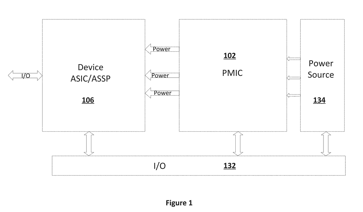
Inactive Publication Date: 2018-12-06
PROGRANALOG
View PDF28 Cites 10 Cited by
  • Summary
  • Abstract
  • Description
  • Claims
  • Application Information

AI Technical Summary

Benefits of technology

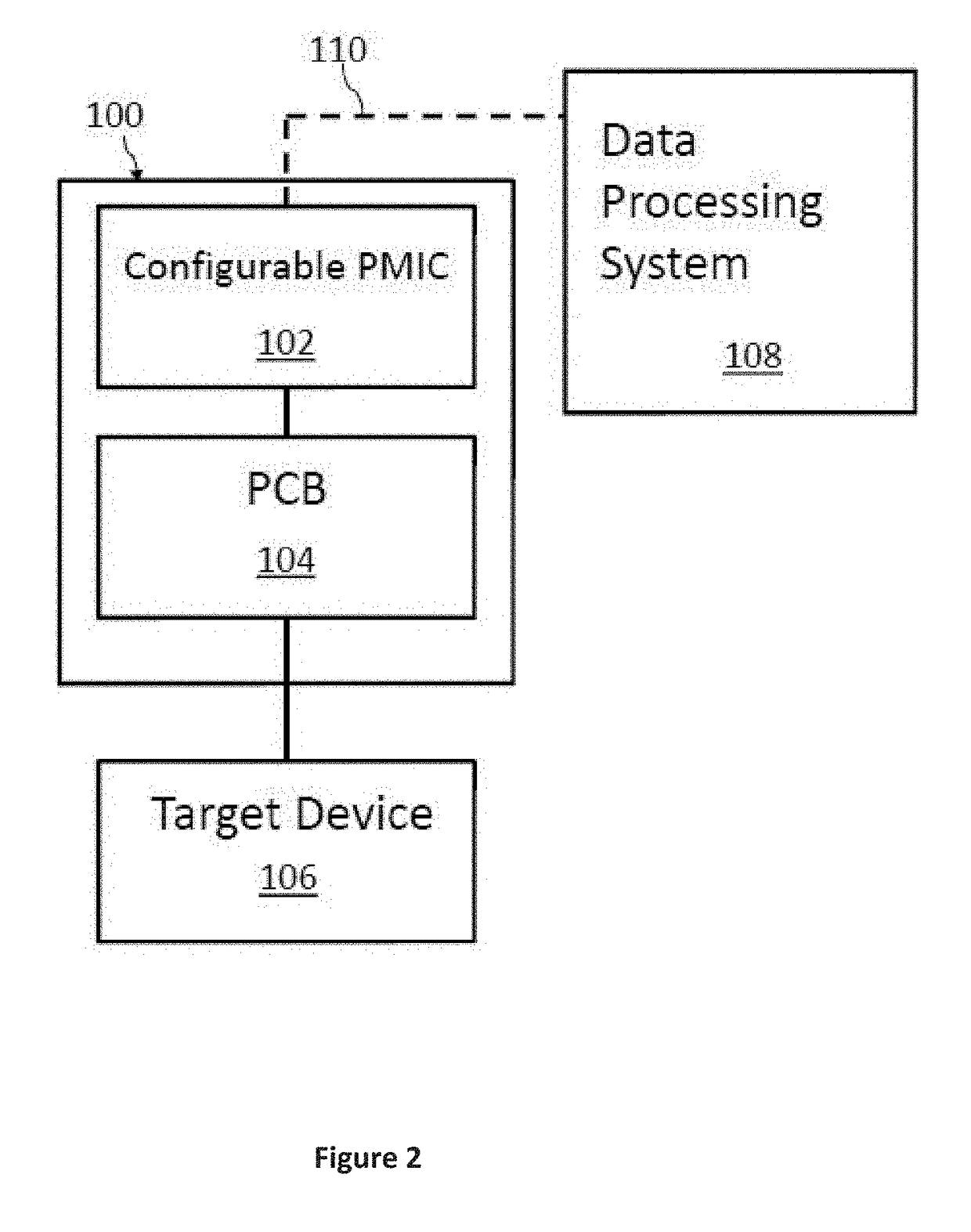
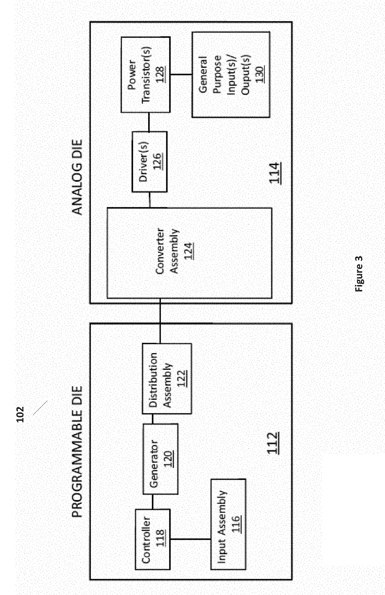
The present invention provides a programmable power management integrated circuit that includes a plurality of cells, each containing at least one driver for a switchable element, and a switch matrix and controller. The switch matrix and controller are programmable to configure at least one power channel, which includes at least one cell of the plurality of cells. The invention allows for the efficient management of power to target devices, providing flexibility in the selection of implementation options and reducing the size of the required power management system. Additionally, a printed circuit board design can also be generated for the integrated circuit.

Problems solved by technology

These loads for different devices often require very sophisticated power supplies.
The result of these two devices being developed in parallel is that unforeseen variables have to be addressed when one or both of the devices return from fabrication and does not work as intended.
The “spin” affects time to market of both devices and, in addition, there is an intrinsic cost of re-design and mask sets.
However, power requirements for a target device may significantly change during its development.
However, once manufactured, existing PMIC devices are not able to compensate for changes in power requirements of a co-developed target device.
Redesigning or remanufacturing a PMIC is costly and significantly increases time-to-market for associated packages.

Method used


Image

  • Configurable power management integrated circuit
  • Configurable power management integrated circuit
  • Configurable power management integrated circuit

Examples


Embodiment Construction

[0030]In the following description, specific details are set forth describing some embodiments of the present invention. It will be apparent, however, to one skilled in the art that some embodiments may be practiced without some or all of these specific details. The specific embodiments disclosed herein are meant to be illustrative but not limiting. One skilled in the art may realize other elements that, although not specifically described here, are within the scope of this disclosure.

[0031]This description and the accompanying drawings that illustrate inventive aspects and embodiments should not be taken as limiting—the claims define the protected invention. Various changes may be made without departing from the scope of this description and the claims. In some instances, well-known structures and techniques have not been shown or described in detail in order not to obscure the invention.

[0032]Elements and their associated aspects that are described in detail with reference to one ...


PUM


Abstract

In accordance with aspects of the present invention, a programmable power management integrated circuit is presented. An integrated circuit can include a plurality of cells, each cell including at least one driver for a switchable element; and a switch matrix and controller coupled to the plurality of cells, the switch matrix and controller being programmable to configure at least one power channel, each power channel including at least one cell of the plurality of cells. A method of providing a power management system using the integrated circuit includes receiving power requirements corresponding to a target device; providing implementation options to achieve the power requirements; selecting a solution from the implementation options; generating a programming file for a power management integrated circuit, and generating a printed circuit board design for the power management integrated circuit.

Description

RELATED APPLICATIONS[0001]The present application claims priority to provisional application Ser. No. 62 / 074,117, filed on Nov. 4, 2014, which is herein incorporated by reference in its entirety.TECHNICAL FIELD[0002]Embodiments of the present invention are related to power management in integrated circuits and, in particular, to configurable power management integrated circuits.DISCUSSION OF RELATED ART[0003]A Power Management Integrated Circuit (PMIC) delivers and manages power for a target electronic device or load, such as an Application Specific Standard Product (ASSP) or an Application Specific Integrated Circuit (ASIC). The PMIC provides the multiple rails that power the accompanying ASIC. There are frequently multiple instantiations of ASICs and ASSPs in one system. Collectively, they are sometimes referred to as target devices. ASICs and ASSPs can require in excess of 10 voltage supplies. In addition to providing the power it often manages the power in a variety of different...

Claims


Application Information

Patent Timeline
Patent Type & Authority Applications(United States)
IPC IPC(8): G06F1/26G06F1/28G06F1/32
CPCG06F1/28G06F1/3296G06F1/3203G06F1/26
Inventor BEESTON, ROGERFISCHER, PHILIPFITE, ROBERT
Owner PROGRANALOG
Learn More