Power factor correction autodetect

a technology of power factor and autodetect, which is applied in the direction of ac-dc conversion, efficient power electronics conversion, electrical apparatus, etc., can solve the problems of not controlling the switch to switch, the pfc pulse width modulator is disabled,

Active Publication Date: 2015-05-21
ACTIVE SEMI
View PDF12 Cites 16 Cited by
  • Summary
  • Abstract
  • Description
  • Claims
  • Application Information

AI Technical Summary

Benefits of technology

[0012]In one example, the standby AC / DC converter has an optocoupler link between the secondary side of the standby AC / DC converter and the primary side of the AC / DC converter. Digital information is sent by a processor powered from the standby power supply voltage, and is communicated across this optocoupler link along with analog feedback information, to the OPTMIC. On the OPTMIC the analog feedback information is used by the standby AC / DC control circuit portion for voltage regulation purposes in the standby AC / DC converter. On the OPTMIC the digital information is communicated to the PFC control circuit portion. In one example the digital information includes the IMON value, the TMON value, the PFC ON bit value and the PFC OFF bit value. Once received, these digital values are then stored in appropriate registers and flip-flops in the PFC control circuit portion. The processor that is powered from the standby supply voltage can therefore configure and control the PFC Autodetect circuit even if the main AC / DC converter is turned off.

Problems solved by technology

If the EN / DISB signal has a second digital logic value, then the PFC pulse width modulator is disabled and does not control the switch to switch.

Method used


Image

  • Power factor correction autodetect
  • Power factor correction autodetect
  • Power factor correction autodetect

Examples


Embodiment Construction

[0024]Reference will now be made in detail to background examples and some embodiments of the invention, examples of which are illustrated in the accompanying drawings.

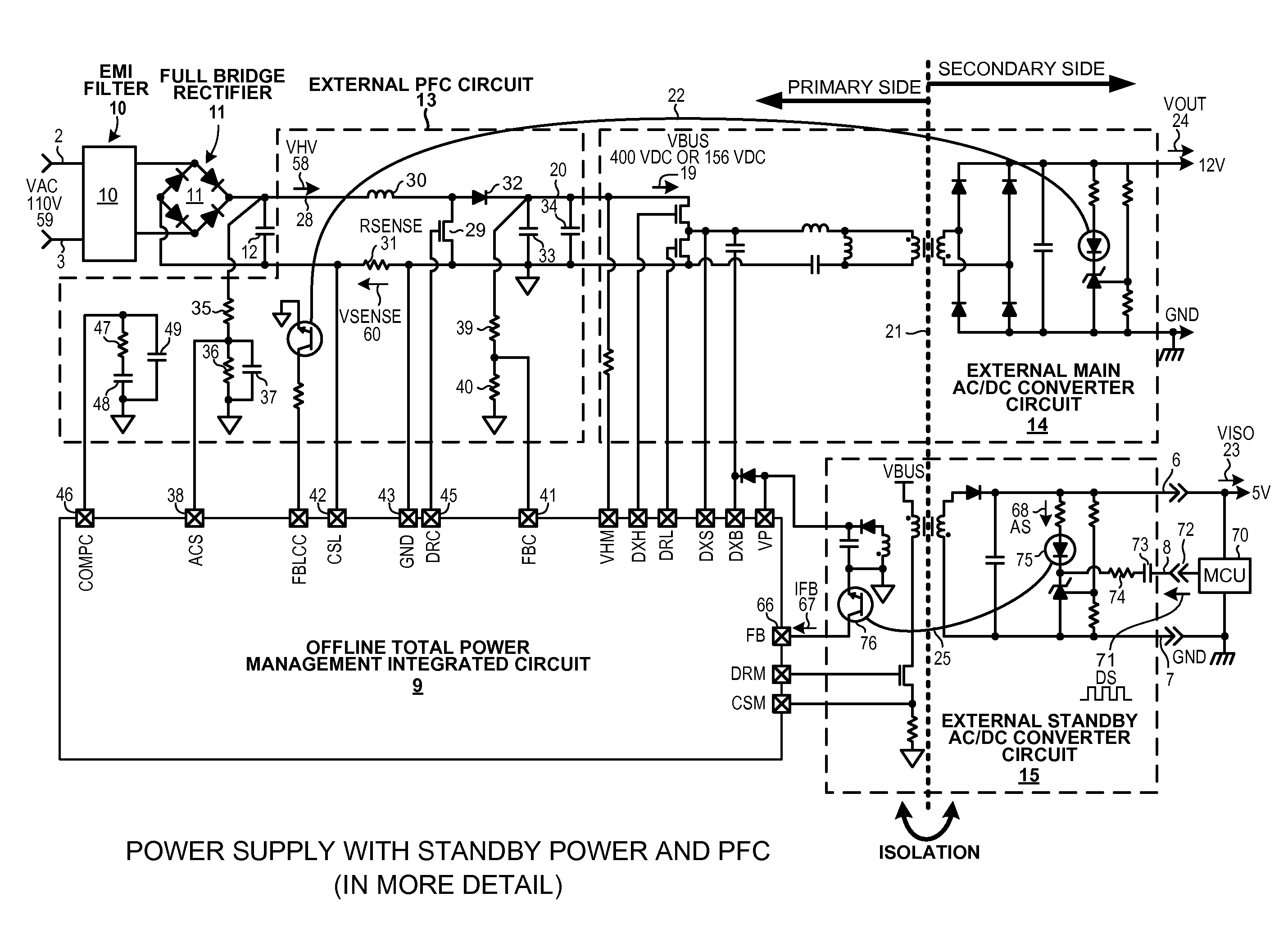
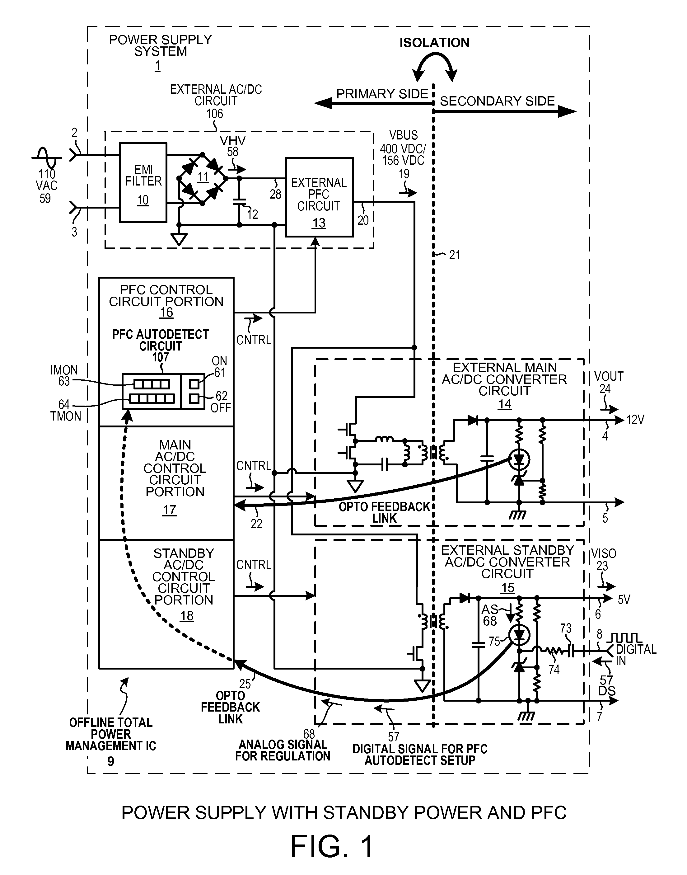
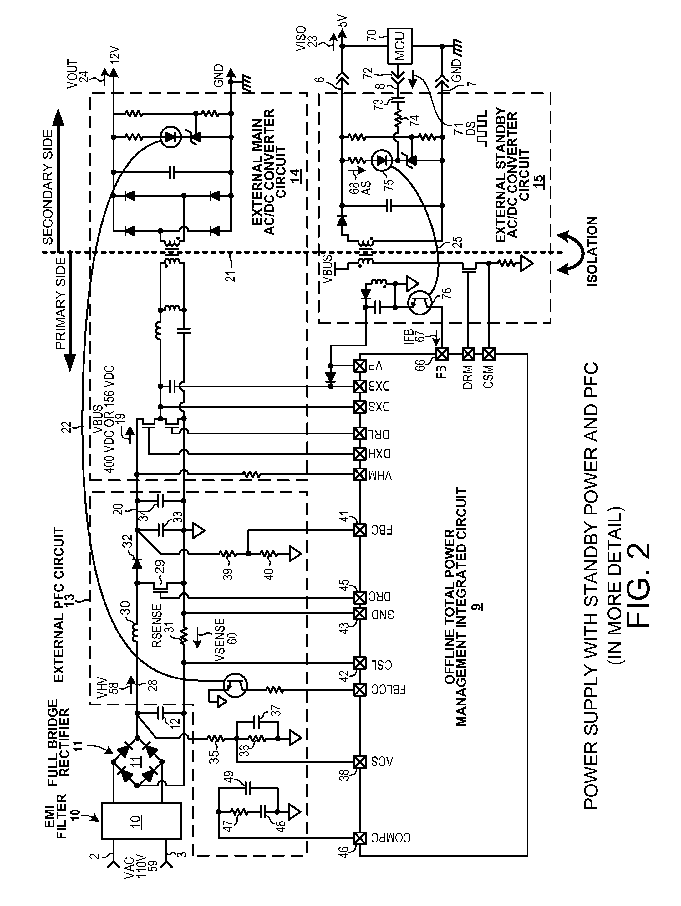
[0025]FIG. 1 is a simplified diagram of a power supply system 1. System 1 includes AC supply voltage input terminals 2 and 3, a first voltage output terminal 4 and ground terminal 5, a second voltage output terminal 6 and ground terminal 7, a digital input terminal 8, an Offline Total Power Management Integrated Circuit (OTPMIC) 9, an EMI filter 10, a full bridge rectifier 11, an input smoothing capacitor 12, an external Power Factor Correction (PFC) circuit 13, an external main AC / DC converter circuit 14, and an external standby AC / DC converter circuit 15. The circuits 13, 14 and 15 are “external” in the sense that they are external to the OTPMIC 9.

[0026]OTPMIC 9 includes a PFC control circuit portion 16, a main AC / DC control circuit portion 17, and a standby AC / DC control circuit portion 18. The PFC control circuit ...


PUM


Abstract

A power supply system includes an Offline Total Power Management Integrated Circuit (OTPMIC). The OTPMIC controls a Power Factor Correction (PFC) converter, a main AC / DC converter, and a standby AC / DC converter. A PFC Autodetect circuit in the OTPMIC monitors current flow in the PFC converter. If a high power condition is detected, then the PFC Autodetect circuit enables the PFC converter. The high power condition may be a voltage drop across a current sense resistor of a predetermined voltage for a predetermined time, within one half period of the incoming AC supply voltage. If a low power condition is detected, then the PFC Autodetect circuit disables the PFC converter. The PFC Autodetect circuit stores an IMON value that determines the predetermined voltage, and a TMON value that determines the predetermined time. The IMON and TMON values are loaded into the Autodetect circuit across an optocoupler link of the standby converter.

Description

TECHNICAL FIELD[0001]The described embodiments relate generally to power factor correction in power supply circuits.BACKGROUND INFORMATION[0002]In some applications, an AC-to-DC power supply is required that receives a single AC (Alternative Current) supply voltage and outputs multiple DC (Direct Current) supply voltages. Some of the DC supply voltages are to be supplied from the power supply at relatively high powers, whereas others may not need to be supplied at such high powers. In some instances, power factor correction is required such that the waveform of the current drawn by the power supply is made to be in phase with the phase of the waveform of the voltage received by the power supply. Improvements in such power supply circuits are desired.SUMMARY[0003]A power supply system includes an input electromagnetic interference (EMI) filter, a bridge rectifier, and an input smoothing capacitor, and a novel Offline Total Power Management Integrated Circuit (OTPMIC). The OTPMIC incl...

Claims


Application Information

Patent Timeline
Patent Type & Authority Applications(United States)
IPC IPC(8): H02M1/42
CPCH02M1/4208H02M1/4225H02M3/33592H02M7/217Y02B70/10H02M1/0012H02M1/0032H02M1/008
Inventor HUYNH, STEVENTRINH, HUE KHACDINH, KHANH QUANGLE, DUONG CONGXIA, DEGANG
Owner ACTIVE SEMI
Why Eureka
Try Eureka