
Eyelash Application System

a technology of eyelash and application system, which is applied in the field of personal care, can solve the problems of health consequences, difficulty in handling requiring a high degree of skill, and affecting the appearance of eyelashes, so as to reduce the skill requirement for use, increase the width, and reduce the effect of skill requirements

Inactive Publication Date: 2018-12-13
SCHROEDER SANDI +1
View PDF10 Cites 25 Cited by
  • Summary
  • Abstract
  • Description
  • Claims
  • Application Information

AI Technical Summary

Benefits of technology

The applicator / tweezer has a rounded end that is closer to the user's wrist and a two-pronged end that is closer to the user's eye. The rounded end allows for better mobility in the hand, while the distal end has a large width and surface area to handle, making it easier for users with less dexterity to use. This allows users to fix multiple fingers along with the thumb and utilize the larger muscles of the arm and wrist, resulting in safer and more precise operation. The technical effect of this design is greater controllability, stability, and ease of use for users.

Problems solved by technology

Current methods for applying, storing, and handling false eyelashes present many problems that range from deleterious health consequences to difficulty in handling requiring a high degree of skill.
Health consequences can result from the false eyelashes coming into contact with bacteria or other contagion eventually infecting the eye.
This can happen when tools are improperly used or sanitized.
This can also happen when an adhesive is applied in an unsanitary way.
Difficulty in applying false eyelashes can result from the awkward use of a delicate tweezer or even from attempting to apply the false eyelash with the naked finger tips.
Solutions have been long sought but prior developments have not taught or suggested any solutions that provide a comprehensive answer to these difficulties, and solutions to these problems have long eluded those skilled in the art.

Method used


Image

  • Eyelash Application System
  • Eyelash Application System
  • Eyelash Application System

Examples


Embodiment Construction

[0024]In the following detailed description of the invention of exemplary embodiments of the invention, reference is made to the accompanying drawings (where like numbers represent like elements), which form a part hereof, and in which is shown by way of illustration specific exemplary embodiments in which the invention may be practiced. These embodiments are described in sufficient detail to enable those skilled in the art to practice the invention, but other embodiments may be utilized and logical, mechanical, electrical, and other changes may be made without departing from the scope of the present invention. The following detailed description is, therefore, not to be taken in a limiting sense, and the scope of the present invention is defined only by the appended claims.

[0025]In the following description, specific details are set forth to provide a thorough understanding of the invention. However, it is understood that the invention may be practiced without these specific details...


PUM


Abstract

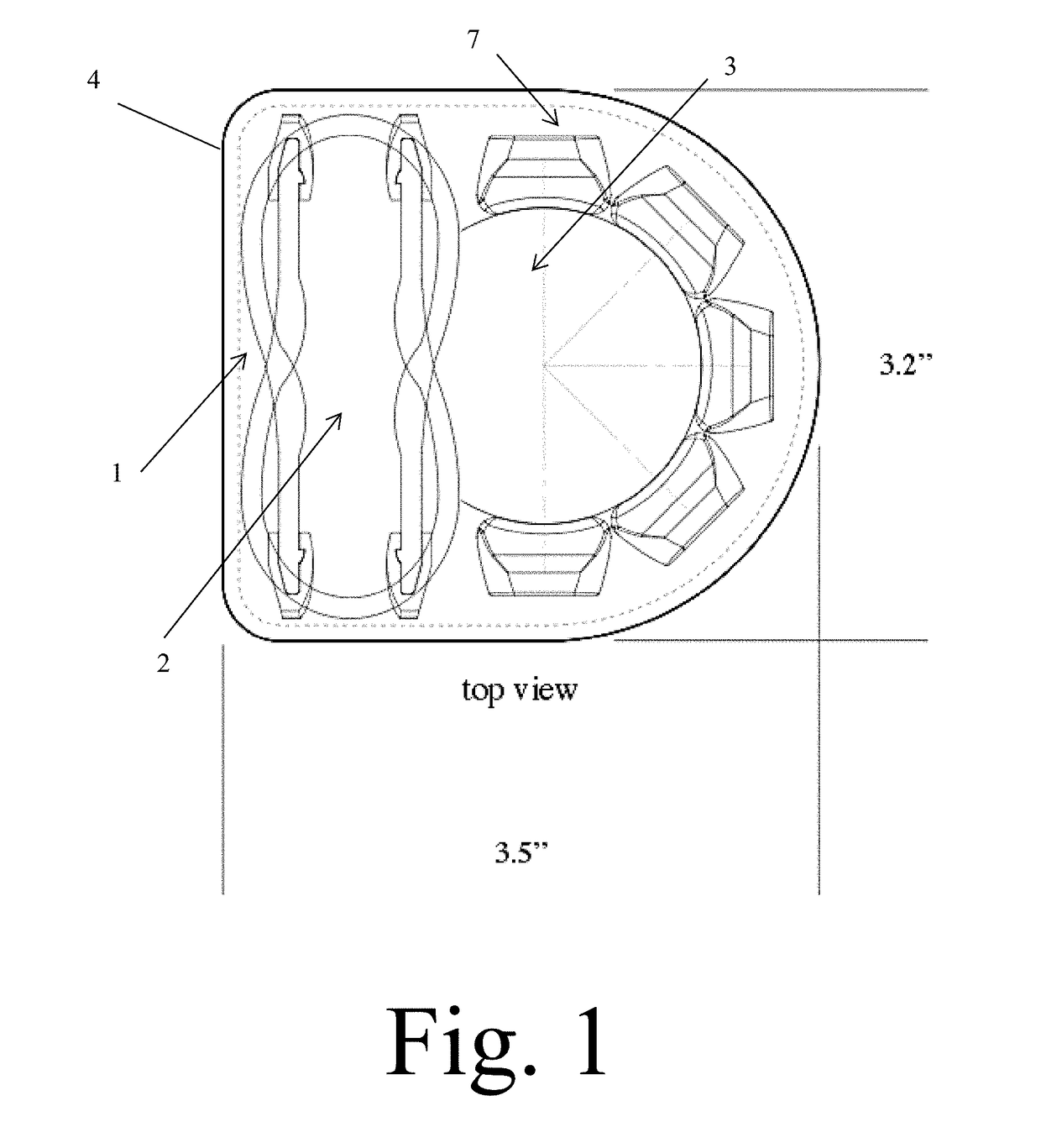
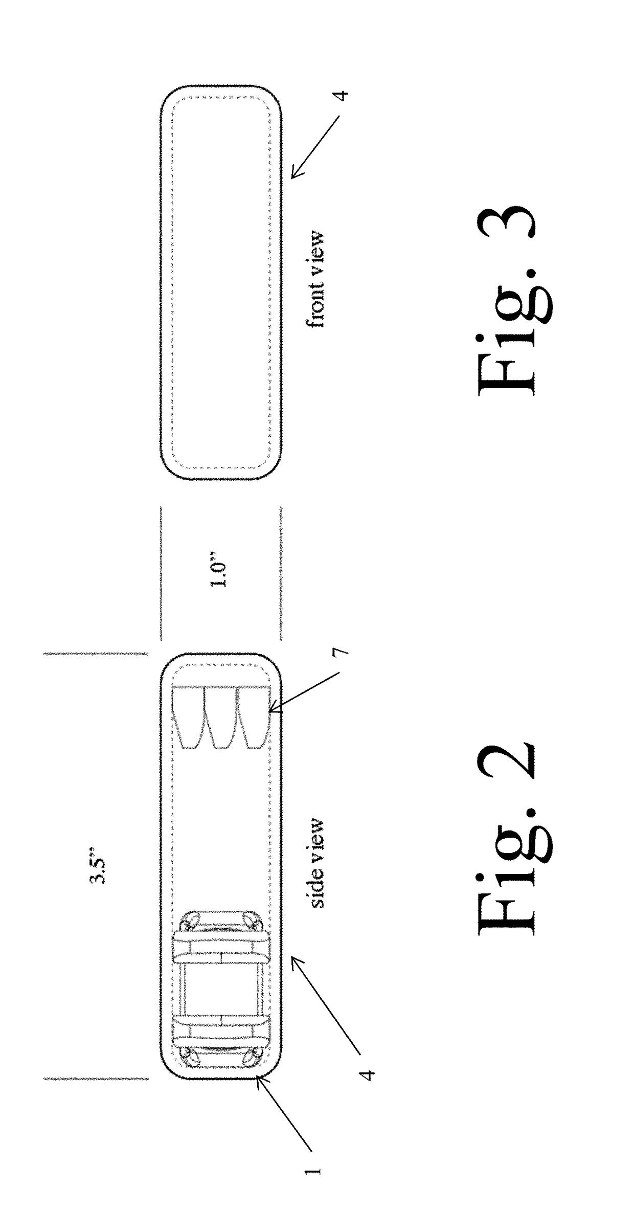
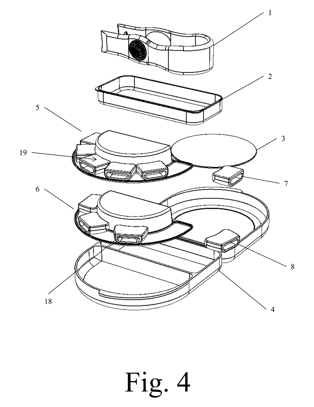
A single folding case that defines two recesses and retains all additional component parts for storage and transport. A first recess of the case is used to retain a mirror on the inner recess surface and provide a recess area for retained other internal component parts. The second recess retaining an applicator / tweezer like eyelash installation tool and rectangular drawer, and a semi-circular recess for retaining two semi-circular eyelash trays. The applicator / tweezer has a rounded proximal end and a two-pronged distal end. In use, a user would take the applicator / tweezer and secure both of the prongs located on the distal end and engage them with the eyelash cartridge. Once the applicator has eyelash cartridges attached, as user would then proceed to press the eyelash on at the desired location. The eyelash would then remain and be retained to the face by glue.

Description

CROSS REFERENCE TO RELATED APPLICATIONS[0001]This application claims priority from U.S. Patent Application Ser. No. 62 / 516,691, entitled “Eyelash Application System”, filed on Jun. 8, 2017. The benefit under 35 USC § 119(e) of the U.S. provisional application is hereby claimed, and the aforementioned application is hereby incorporated herein by reference.[0002]This application is related to U.S. patent application Ser. No. 14 / 476,746 filed on Sep. 4, 2014, now U.S. Pat. No. 9,215,901 issued on Dec. 22, 2015, entitled “Eyelash application system”, filed on 6 Jun. 2016.FEDERALLY SPONSORED RESEARCH[0003]Not ApplicableSEQUENCE LISTING OR PROGRAM[0004]Not ApplicableTECHNICAL FIELD OF THE INVENTION[0005]The present invention relates in general to systems and methods for personal care. More specifically, the present invention relates to systems and methods for personal care, more partially for handling, storing, and applying false eyelashes.BACKGROUND OF THE INVENTION[0006]People around th...

Claims


Application Information

Patent Timeline
IPC IPC(8): A41G5/02
CPCA41G5/02A45D42/04A45C11/008A45D26/0066
Inventor SCHROEDER, SANDIHARRIS, DAVID
Owner SCHROEDER SANDI
Learn More