Operational monitoring system

a monitoring system and operation technology, applied in the field of monitoring systems, can solve the problems of supervisors lacking the details necessary to make informed decisions about each construction site, inconvenient monitoring, and inability to provide complete or incorrect information, so as to achieve the effect of determining efficiency and reliability of workers

Inactive Publication Date: 2018-12-13
OPTICAL OPERATIONS LLC
View PDF3 Cites 7 Cited by
  • Summary
  • Abstract
  • Description
  • Claims
  • Application Information

AI Technical Summary

Benefits of technology

The present invention is an operating monitoring system for a construction work-site. This system uses cameras placed around the work-site to capture images, which are then transmitted to a server to create a 3D model of the work-site. The system also includes a tracking system to record information on workers and equipment, such as their positions and movements. This information helps the system determine the efficiency and reliability of workers and equipment. Additionally, the system allows for the assignment of tasks and zones to workers, and provides real-time monitoring of progress through an interactive display system. The system can automatically alert supervisors of certain conditions, such as accidents and equipment failures. Overall, the invention helps streamline construction work-sites and improves safety compliance.

Problems solved by technology

This is time-consuming, inaccurate, and inefficient as the information received by the supervisor must be relayed to the supervisor by another person present on-site, which inherently leads to incomplete or incorrect information being provided.
The relayed information that is provided is naturally retrospective, which further diminishes the value of the provided information.
The need for the supervisor to be on-site leads to other issues.
This is especially true given the numerous changes that can occur while the supervisor isn't present, such as delayed shipments, conflicts in schedules, and tardy or absent contractors.
As a result, a supervisor lacks the details necessary to make informed decisions related to each construction site.
For instance, the use of GPS is limited and difficult to interpret in relation to a project, which is fluid in nature as progress is made.
Moreover, the mere presence of a piece of machinery or equipment provides little to no value with respect to the work being completed.
Video feeds have also been utilized, but it is often difficult, if not impossible, to discern what a particular worker is doing.
However, the different designated areas are often too large and encompasses an area that multiple, widely varying tasks are being worked on and provide no way of knowing where a worker is within a particular area.
Further, the use of digital punch cards can require the setup and maintenance of multiple entry ways that require workers to go out of their way to punch-in once they have arrived to work.
However, the localization of this information dramatically reduces its usefulness as machinery may break down and not be addressed until the next time the supervisor is on-site, or is called back by someone on-site.

Method used


Image

  • Operational monitoring system
  • Operational monitoring system
  • Operational monitoring system

Examples


Embodiment Construction

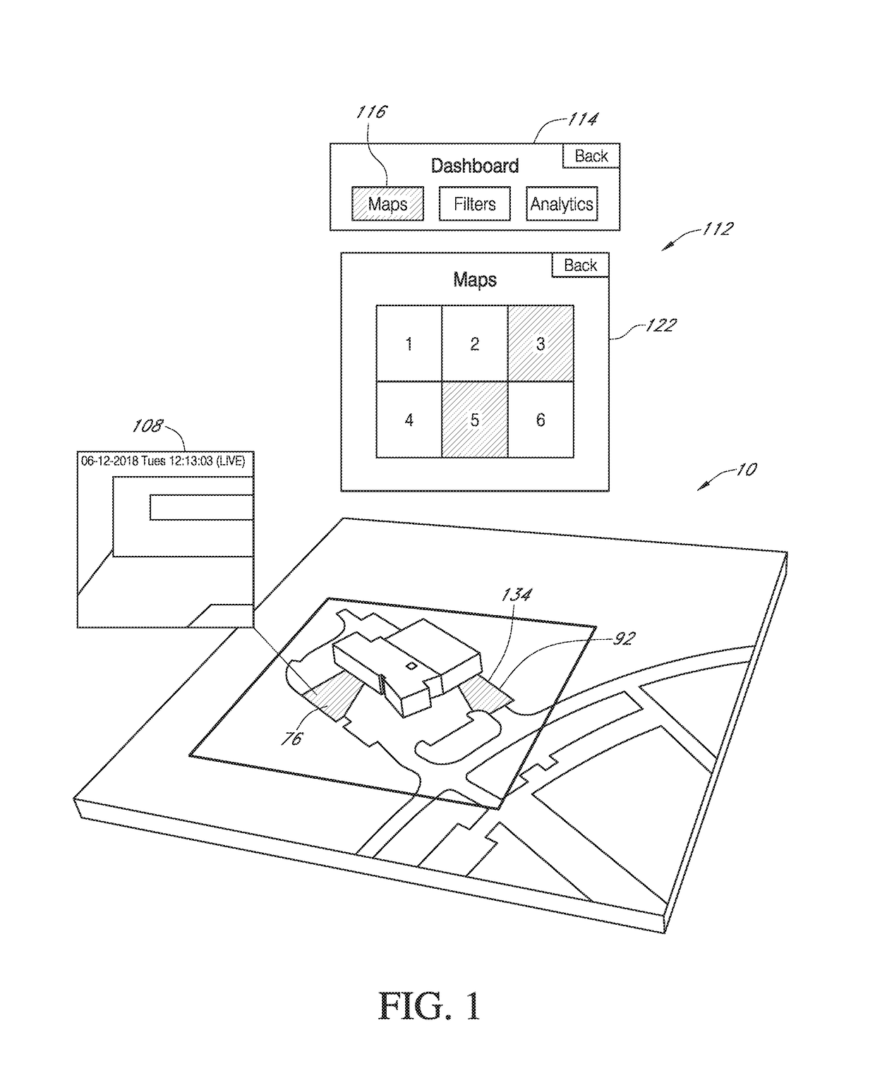
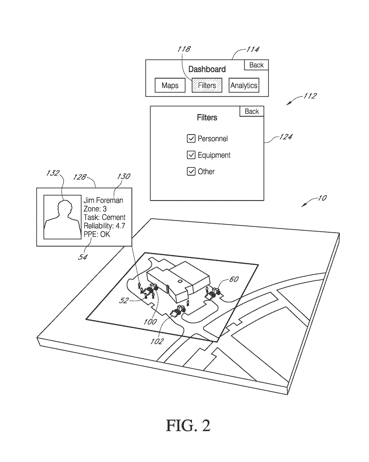
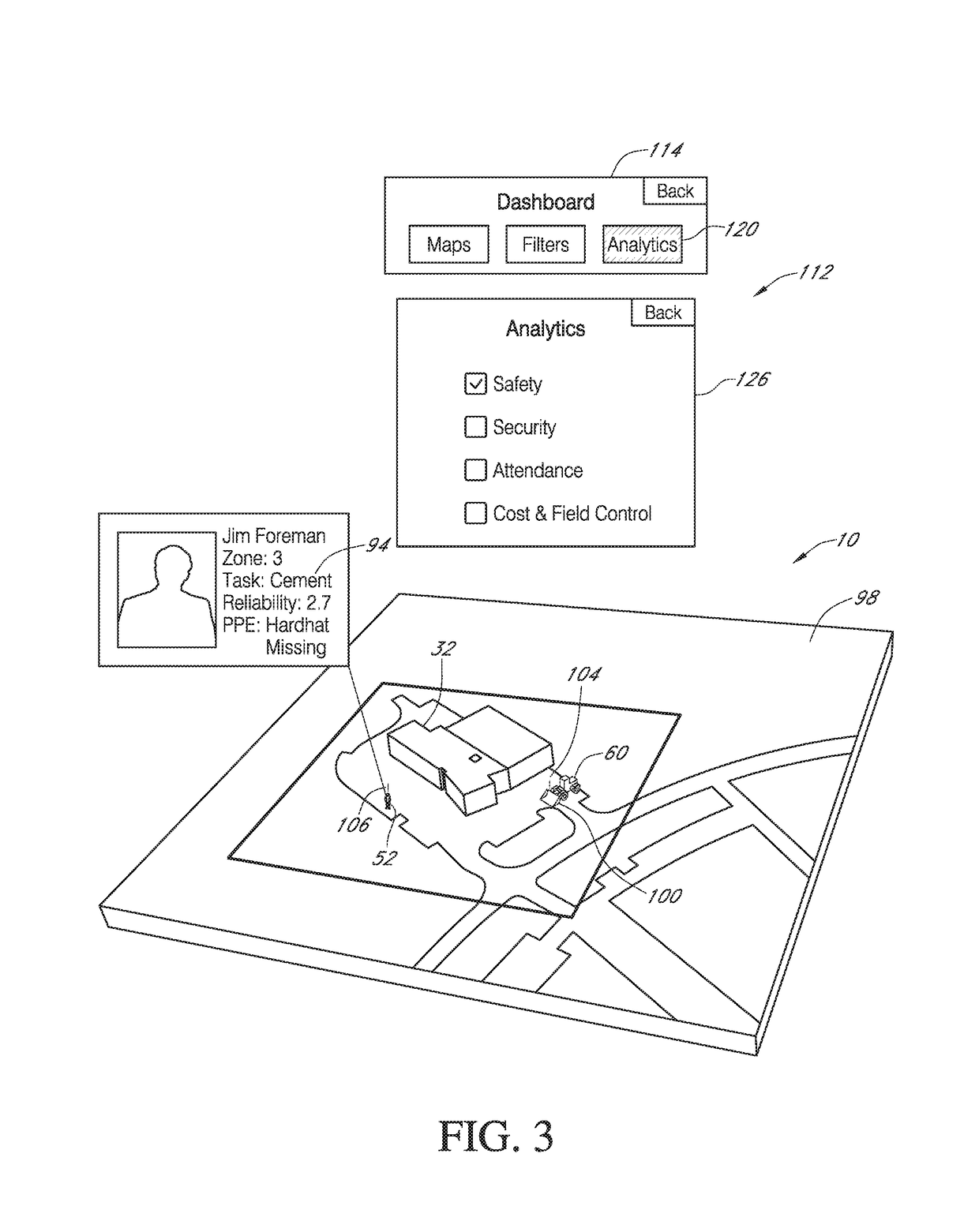
[0031]With reference to the figures an operational monitoring system 10 is shown having a site rendering system 12, a personnel tracking system 14, an equipment tracking system 16, and a supervisory system 18.

[0032]The site rendering system 12 has a plurality of cameras 20 having positions around a work-site 22. The cameras 20 are configured to capture one or more images 24 that overlap with one another. The images 24 are transferred from the cameras 20 by a wireless device 26 on each camera 20 to a server 28 that is either at the work-site 22 or at a remote location 30 from the work-site 22. The wireless device 26 can be WiFi, Bluetooth, cellular, or other long-range or near-field communication (NFC) device.

[0033]The server 28 processes the images 24 using photogrammetry, which analyzes and extracts information from the images 24 to render a 3D model 32 of the work-site 22. In some instances, the server 28 renders a 2D Model 34. A LiDar (laser scanning) device or micro optical mech...


PUM


Abstract

The present invention relates to an operational monitoring system that collects information in real-time from a work-site with a personnel tracking system, an equipment tracking system. The collected information is sent to a server, which is received and presented on an interactive display system that uses information capture by a site rendering system to render a 3D model of the work-site. A task management system allows an end-user to assign work profiles, tasks, and zones for workers and equipment operating on-site, which is thereafter monitored in real-time.

Description

CROSS REFERENCE TO RELATED APPLICATION[0001]This application claims the benefit of U.S. Provisional Application No. 62 / 518,183 filed Jun. 12, 2017.BACKGROUND OF THE INVENTION[0002]This invention is directed toward a monitoring system. More specifically, and without limitation, this invention relates to an operational monitoring system for providing real-time or near real-time monitoring of construction sites.[0003]Presently, to monitor one or more construction sites requires that a general contractor or supervisor conduct an on-site visit for each site. This is time-consuming, inaccurate, and inefficient as the information received by the supervisor must be relayed to the supervisor by another person present on-site, which inherently leads to incomplete or incorrect information being provided. The relayed information that is provided is naturally retrospective, which further diminishes the value of the provided information. This process must be repeated for each construction site be...

Claims


Application Information

Patent Timeline
Patent Type & Authority Applications(United States)
IPC IPC(8): G06Q10/06G06F13/42H04N7/18G06T17/05
CPCG06Q10/06311G06F13/4282H04N7/181G06T17/05G06T2200/08
Inventor GUILLEMETTE, ANDREW
Owner OPTICAL OPERATIONS LLC
Why Eureka
Try Eureka