Magnetic sensor using spin hall effect

Active Publication Date: 2018-12-13
WESTERN DIGITAL TECH INC
View PDF6 Cites 17 Cited by
  • Summary
  • Abstract
  • Description
  • Claims
  • Application Information

AI Technical Summary

Problems solved by technology

However, achieving the smaller spaci

Method used


Image

  • Magnetic sensor using spin hall effect
  • Magnetic sensor using spin hall effect
  • Magnetic sensor using spin hall effect

Examples


Embodiment Construction

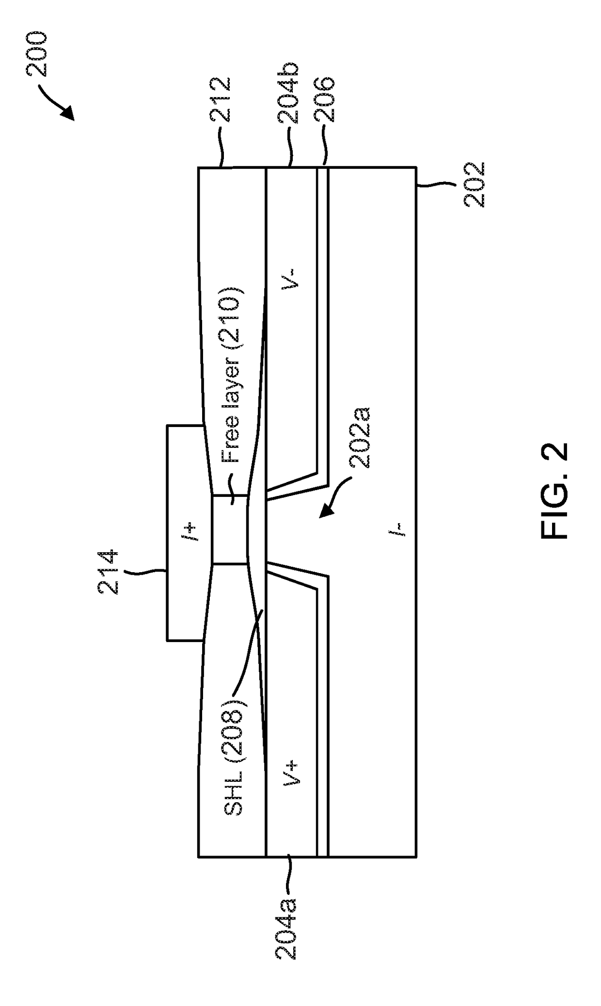
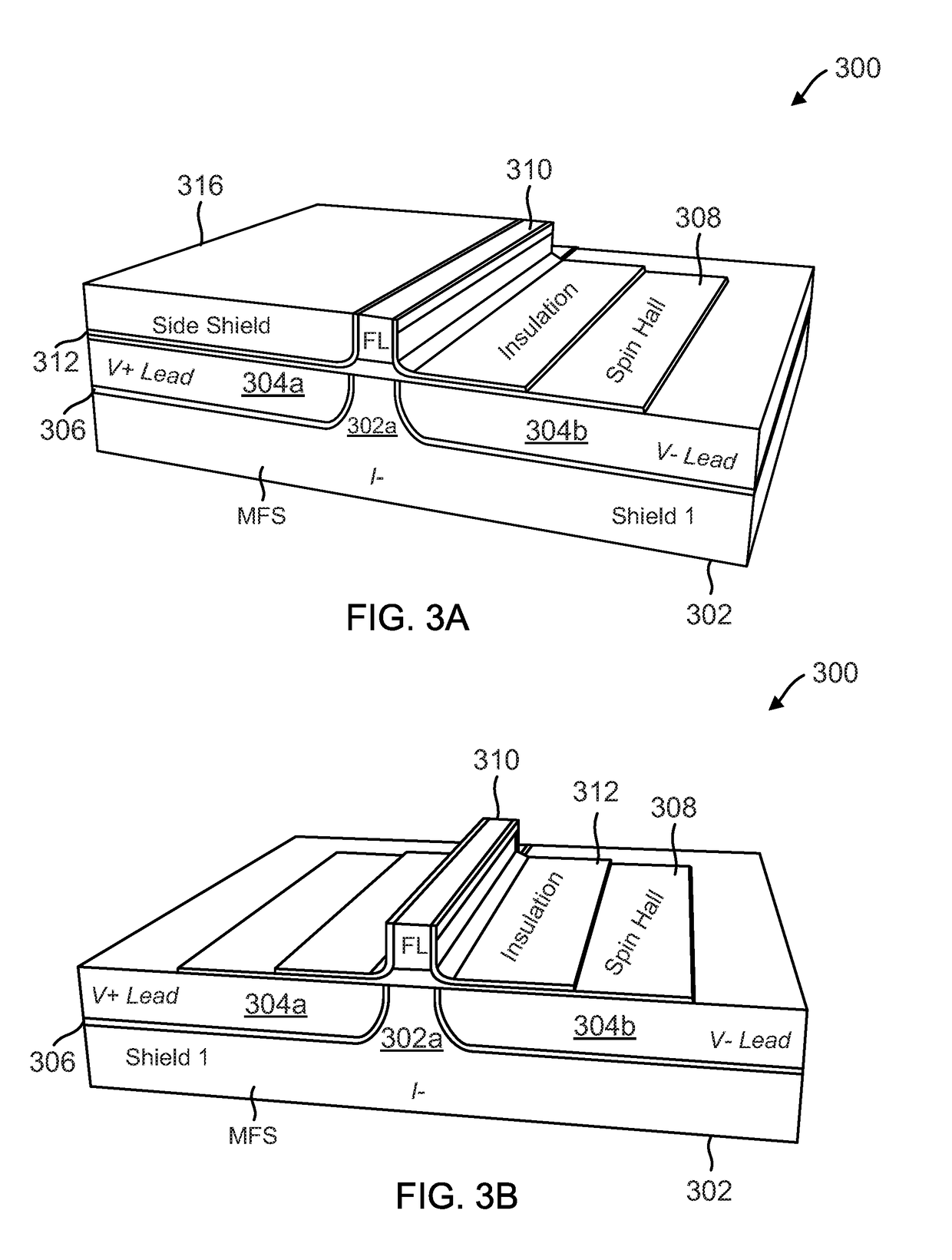
[0020]To address the problems described above, spin Hall effect (SHE) sensors are proposed with a narrower reader gap than conventional sensors. Referring now to the drawings, embodiments of sensors and fabrication methods for sensors having narrow reader gap are illustrated. In one aspect, these sensors feature a thin stack by having one free layer and one spin Hall layer. In one aspect, the thin stack, which corresponds with a narrow reader gap, may be achieved by electrically isolating terminals of the sensor. In one aspect, the sensors can include a pair of push terminals configured to enable an electrical current to pass through the magnetic free layer and the spin Hall layer in a direction that is perpendicular to a plane of the free and spin Hall layers, and a pair of sensing terminals configured to sense a voltage when the electrical current passes through the magnetic free layer and the spin Hall layer. In several aspects, these terminals can be isolated. In one aspect, a p...


PUM


Abstract

Magnetic sensors using spin Hall effect and methods for fabricating same are provided. One such magnetic sensor includes a spin Hall layer including an electrically conductive, non-magnetic material, a magnetic free layer adjacent to the spin Hall layer, a pair of push terminals configured to enable an electrical current to pass through the magnetic free layer and the spin Hall layer in a direction that is perpendicular to a plane of the free and spin Hall layers, and a pair of sensing terminals configured to sense a voltage when the electrical current passes through the magnetic free layer and the spin Hall layer, where each of the push and sensing terminals is electrically isolated from the other terminals.

Description

CROSS-REFERENCE TO RELATED APPLICATION(S)[0001]This application is a continuation of U.S. patent application Ser. No. 62 / 518,540, filed on Jun. 12, 2017, having Attorney Docket No. SDA-3257P-US (WDT-1208P) and entitled, “MAGNETIC SENSOR USING SPIN HALL EFFECT”, the entire content of which is incorporated herein by reference.FIELD[0002]The present invention relates to magnetic data recording and more particularly to a magnetic read sensor that utilizes spin Hall effect to detect the presence of a magnetic field.INTRODUCTION[0003]Computer systems commonly include an assembly that is referred to as a magnetic disk drive. The magnetic disk drive includes a rotating magnetic disk, write and read heads that are suspended by a suspension arm adjacent to a surface of the rotating magnetic disk and an actuator that swings the suspension arm to place the read and write heads over selected tracks on the rotating disk. The read and write heads are directly located on a slider that has an air be...

Claims


Application Information

Patent Timeline
IPC IPC(8): H01L43/06H01L43/04H01L43/08H01L43/10H01L43/14H01L27/22G11C11/16G11C11/18H01F10/32G11B5/012
CPCH01L43/06H01L43/04H01L43/08H01L43/10H01L43/14H01L27/222G11C11/161G11C11/18H01F10/329H01F10/3286G11B5/012G01R33/07G01R33/09G01R33/1284G11B5/372G11B5/3903H10N52/00H10N52/01H10N50/10H10B61/00H10N50/85H10N52/80
Inventor LE, QUANGSEAGLE, DAVID JOHNLIU, XIAOYONGMAURI, DANIELEAHN, YONGCHULJIANG, HONGQUANLIU, GUANGLIDRUIST, DAVID PATRICKLI, JUI-LUNG
Owner WESTERN DIGITAL TECH INC
Why Eureka
Try Eureka