Dc-to-dc converter circuit and circuit board layout structure for the same

Active Publication Date: 2018-12-13
DELTA ELECTRONICS INC
View PDF7 Cites 1 Cited by
  • Summary
  • Abstract
  • Description
  • Claims
  • Application Information

AI Technical Summary

Benefits of technology

The present patent application provides a DC-to-DC converter circuit that is connected between two power supplies. It includes two branches, each with a primary side and a secondary side. The secondary sides of the branches are connected in series through a first inductor. The circuit allows for the efficient transfer of power between the two power supplies, reducing power loss and improving overall efficiency. The patent also provides a circuit board layout structure for the DC-to-DC converter circuit, which allows for the proper placement of components on the circuit board to ensure optimal performance.

Problems solved by technology

Although such a circuit structure may achieve a higher output power, it has some drawbacks in use.
Therefore, an increased jump frequency of the voltage may increase radiation interferences and common-mode currents, and deteriorate the electromagnetic interference (EMI) performance.

Method used


Image

  • Dc-to-dc converter circuit and circuit board layout structure for the same
  • Dc-to-dc converter circuit and circuit board layout structure for the same
  • Dc-to-dc converter circuit and circuit board layout structure for the same

Examples


first embodiment

[0022]a DC-to-DC converter circuit according to the present application will be described below.

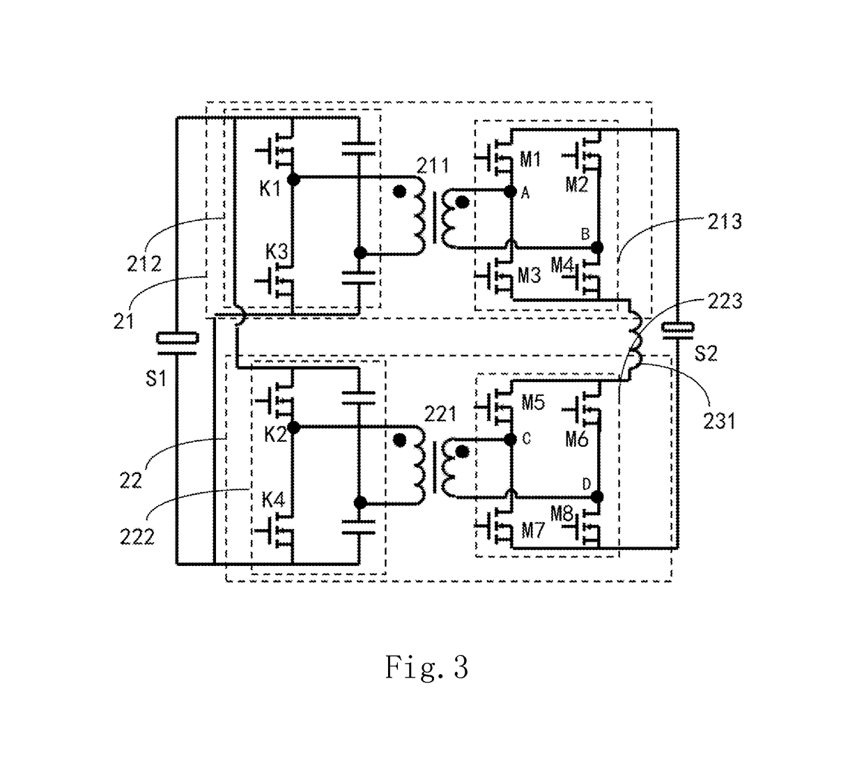
[0023]Referring to FIG. 3, FIG. 3 is a schematic diagram of the first embodiment of the DC-to-DC converter circuit according to the present application. As shown in FIG. 3, the DC-to-DC converter circuit according to the present application is electrically connected between a first power supply side 51 and a second power supply side S2. The converter circuit comprises a first branch 21, a second branch 22, and a first inductor 231. The primary sides of the first branch 21 and the second branch 22 are coupled to the first power supply side 51. The secondary sides of the first branch 21 and the second branch 22 are coupled to the second power supply side S2. The secondary sides of the first branch 21 and the second branch 22 are connected in series via the first inductor 231.

[0024]The first branch 21 comprises a first transformer 211, a first primary switching circuit 212, and a first secon...

second embodiment

[0030]a DC-to-DC converter circuit according to the present application will be described below.

[0031]Referring to FIG. 6, FIG. 6 is a schematic diagram of the second embodiment of the DC-to-DC converter circuit according to the present application. The structure of the converter circuit shown in FIG. 6 is substantially the same as that shown in FIG. 3. Thus, the description for similar elements in FIGS. 6 and 3 will be omitted here. The following description mainly focuses on the difference between them. The converter circuit shown in FIG. 6 further comprises a third branch 24 and a second inductor 232. The primary sides of the first branch 21, the second branch 22, and the third branch 24 are electrically connected, and then coupled to the first power supply side S1. The secondary sides of the first branch 21, the second branch 22, and the third branch 24 are coupled to the second power supply side S2. The secondary sides of the first branch 21 and the second branch 22 are connect...

third embodiment

[0039]a DC-to-DC converter circuit according to the present application will be described below.

[0040]Referring to FIG. 7, FIG. 7 is a schematic diagram of the third embodiment of the DC-to-DC converter circuit according to the present application. As shown in FIG. 7, each the first branch 21 and the second branch 22 may have a forward topology structure, such as an active-clamped forward topology structure. The primary sides of the first branch 21 and the second branch 22 are coupled to the first power supply side S1. The secondary sides of the first branch 21 and the second branch 22 are coupled to the second power supply side S2. The secondary sides of the first branch 21 and the second branch 22 are connected in series via the first inductor 231.

[0041]Further, the first primary switching circuit 212 of the first branch 21 comprises two switching tubes K1 and K3. The second primary switching circuit 222 of the second branch 22 comprises two switching tubes K2 and K4. The phase di...


PUM


Abstract

The present application discloses a DC-to-DC converter circuit and a circuit board layout structure for the same. The DC-to-DC converter circuit is electrically connected between a first power supply side and a second power supply side, and comprises a first branch with a primary side coupled to the first power supply side and a secondary side coupled to the second power supply side; a second branch with a primary side coupled to the first power supply side and a secondary side coupled to the second power supply side; and a first inductor. The secondary sides of the first branch and the second branch are connected in series via the first inductor.

Description

CROSS-REFERENCE TO RELATED APPLICATIONS[0001]This non-provisional application claims priority under 35 U.S.C. § 119(a) on Patent Application No. 201710433641.X filed in P.R. China on Jun. 9, 2017 and Patent Application No. 201711236708.7 filed in P.R. China on Nov. 30, 2017, the entire contents of which are hereby incorporated by reference.[0002]Some references, if any, which may include patents, patent applications and various publications, may be cited and discussed in the description of this invention. The citation and / or discussion of such references, if any, is provided merely to clarify the description of the present invention and is not an admission that any such reference is “prior art” to the invention described herein. All references listed, cited and / or discussed in this specification are incorporated herein by reference in their entireties and to the same extent as if each reference was individually incorporated by reference.BACKGROUND OF THE INVENTION1. Field of the Inv...

Claims


Application Information

Patent Timeline
IPC IPC(8): H02M3/28H05K1/18H02M1/14
CPCH02M3/28H05K1/181H02M1/14H05K2201/1003H05K2201/10053H02M1/44H02M3/3372H05K1/0263H02M1/0077H02M1/123
Inventor LU, SHENGLIXIA, YANBINGLI, WENHUA
Owner DELTA ELECTRONICS INC
Why Eureka
Try Eureka