

Elliptical drive system
- Summary
- Abstract
- Description
- Claims
- Application Information
AI Technical Summary
Benefits of technology
Problems solved by technology
Method used
Image

Examples
Embodiment Construction
[0023]Detailed descriptions of the preferred embodiment are provided herein. It is to be understood, however, that the present invention may be embodied in various forms. Therefore, specific details disclosed herein are not to be interpreted as limiting, but rather as a basis for the claims and as a representative basis for teaching one skilled in the art to employ the present invention in virtually any appropriately detailed system, structure or manner.
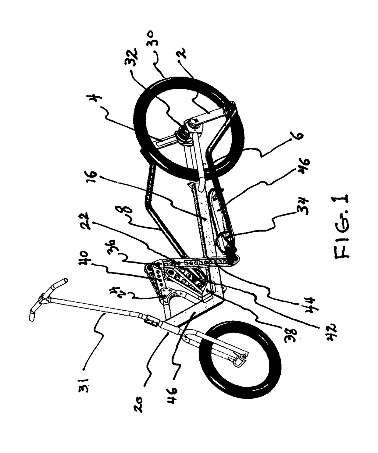
[0024]FIG. 1 is a perspective view of the invention. The linkage of the present invention is attached to standard pneumatic wheels 30 and steering column 31. Left and right rear crank arms 2, 4 are fixedly attached to the central hub 32 of the rear wheel 30. The linkage shown in the present invention includes left and right identical components that mirror each other. However, for simplicity sake, the following description may in some cases refer to the right side linkage only, with the understanding that the left side linkage operat...
PUM
 Abstract
Description
Claims
Application Information