
Pressure sensor and sensor system comprising one or more pressure sensors

a technology of pressure sensor and sensor system, which is applied in the direction of fluid pressure measurement by electric/magnetic elements, measurement devices, instruments, etc., can solve the problems of affecting the accuracy of pressure monitoring over a period of time, and affecting the accuracy of pressure monitoring

Active Publication Date: 2018-12-20
OPTICS11 BV
View PDF6 Cites 6 Cited by
  • Summary
  • Abstract
  • Description
  • Claims
  • Application Information

AI Technical Summary

Benefits of technology

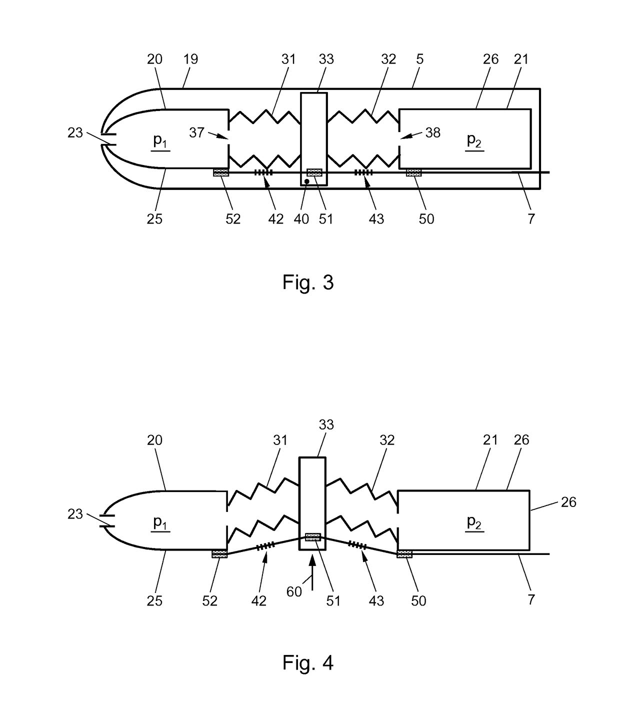
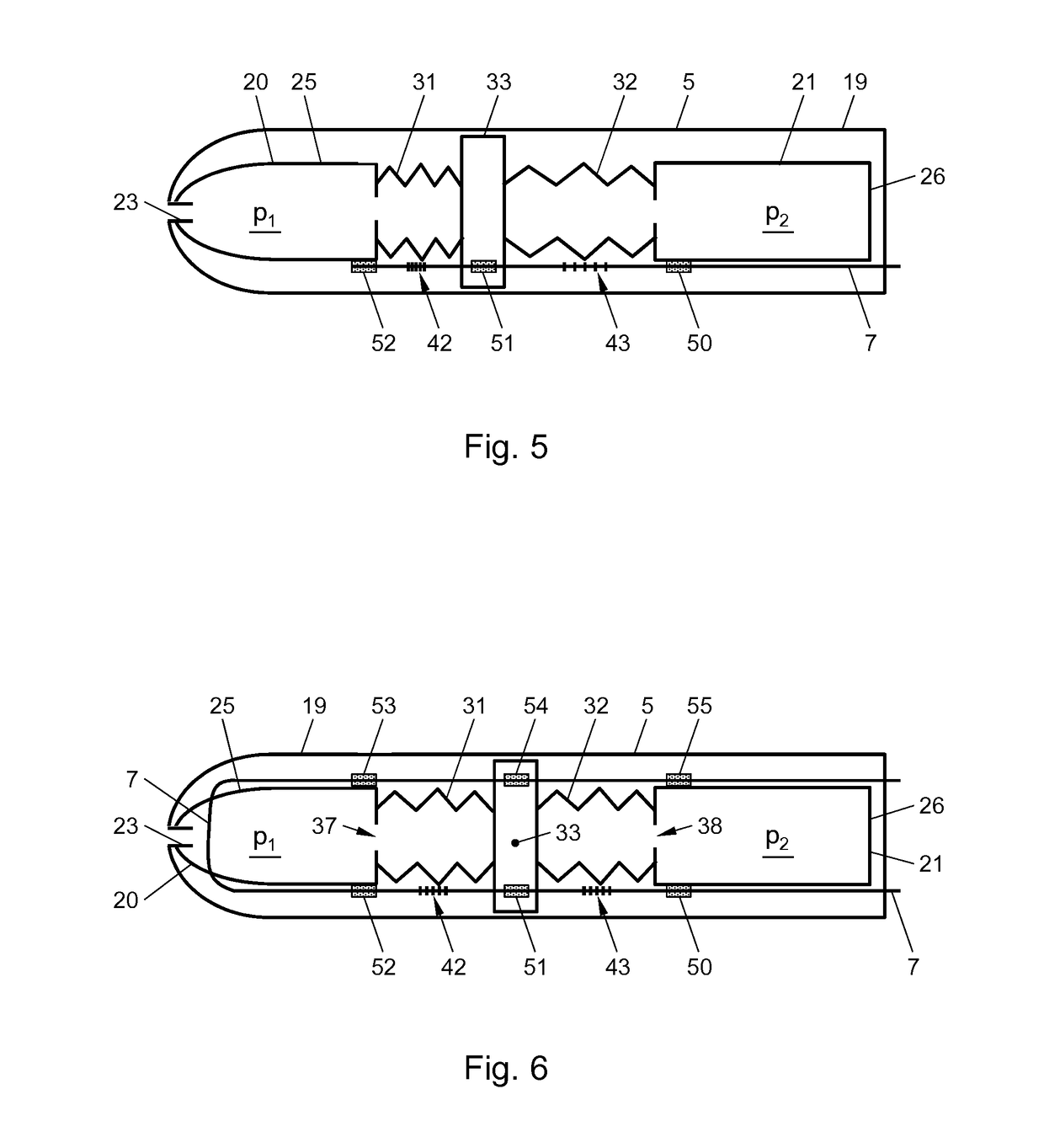
The present invention provides a pressure sensor that overcomes the disadvantages of previous configurations by accurately monitoring pressure over a period of time. The sensor is designed to be less sensitive to external vibrations and can provide accurate readings even in the presence of sideways vibrations. The sensor includes a fiber optic sensor that is pre-stressed to provide a wider range of pressures that can be measured. The fiber is located exterior to the bellows of the sensor to prevent exposure to gases and other substances that may affect its performance. The sensor is designed to minimize deformation caused by external pressure and can provide accurate readings even in situations where there is no fluid connection between the sensor and the external environment. The sensor can also be designed to minimize interference caused by sideways vibrations.

Problems solved by technology

This results in a relative vibration of the interposed section in relation to the first and second part.
The above will not be achievable in an unbalanced configuration (i.e. as in the prior art) where the movement of a deformable element in response to sideways vibration will cause a different and in most cases an error that cannot be removed from the measurements.
In other words, from any arbitrary vibration exerted on the pressure sensor, only the (small) component aligned with the intrinsic fiber optic sensor may result in a noticeable change in the optical signal.

Method used


Image

  • Pressure sensor and sensor system comprising one or more pressure sensors
  • Pressure sensor and sensor system comprising one or more pressure sensors
  • Pressure sensor and sensor system comprising one or more pressure sensors

Examples


Embodiment Construction

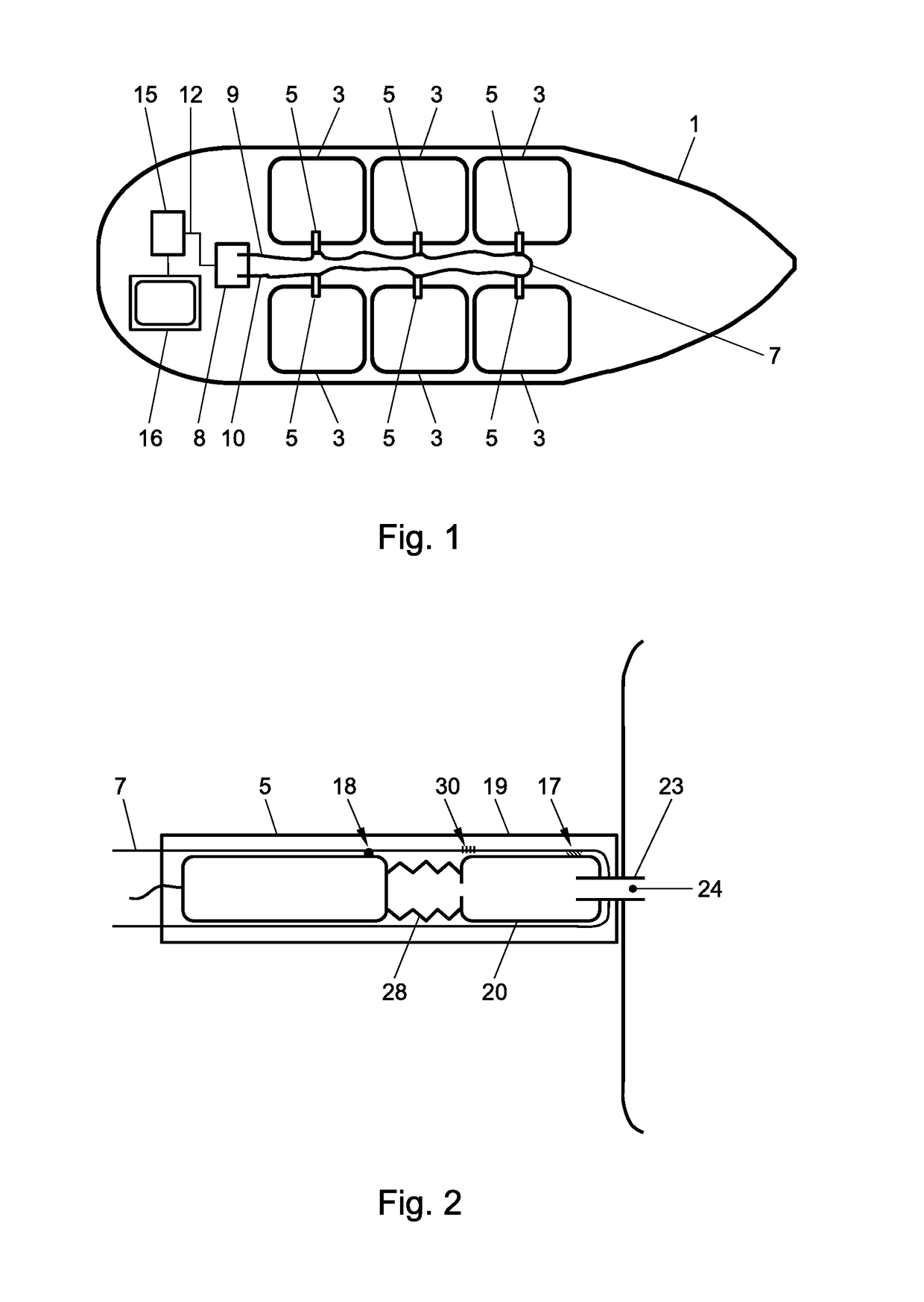
[0040]The pressure sensors and sensor systems described in this document may be applied in many different types of applications and are not intendent to be limited to any of the particular applications that are described herein. As an example, a specific application of a pressure system in an oil tanker 1 is schematically illustrated in FIG. 1. A skilled person will however appreciate that pressure sensors may be applied in many different situations in all kinds of industry and scientific applications, such as to measure or monitor fluid pressures for example in fluids such as gasses or liquids. The pressure sensors in accordance with the present invention can be applied both as absolute pressure sensors to determine an absolute pressure of a fluid, for example tuned to a specific measurement range of pressures. Alternatively, the pressure sensors in accordance with the present invention may also be applied to measure differential pressures, e.g. pressure differences between the fir...


PUM


Abstract

The present document relates to a pressure sensor comprising a structural element, the structural element comprising a first and second structural part. The sensor further comprises a first cavity being in fluid connection with an exterior of the sensor for establishing a first pressure which is dependent on an external pressure in the first cavity and a second cavity configured to be at a second pressure in use. A deformable structure is deformable dependent on a pressure difference between the first pressure and the second pressure. The sensor comprises a fiber including an intrinsic fiber optic sensor fixed to the structural element and to the deformable structure for providing an optical sensor signal dependent on said pressure difference.

Description

FIELD OF THE INVENTION[0001]The present invention is directed at a sensor for sensing a physical parameter, such as a pressure sensor. The present invention is further directed at a sensor system comprising one or more of pressure sensors as described above.BACKGROUND[0002]In the field of sensors, the sensors that apply an intrinsic fiber optic sensor unit are known to potentially provide a very accurate reading of the pressure to be measured. This is due to the accuracy of intrinsic fiber optic sensors themselves. An intrinsic fiber optic sensor is a sensor that comprises an optical fiber that is lit with an optical signal. Any changes to the fiber caused by external factors, such as mechanically induced forces on the fiber, can be accurately sensed by monitoring the characteristics of the optical signal using an interrogator.[0003]To allow monitoring of a physical parameter, such as the pressure, some known types of sensors apply a structural element comprising two structural part...

Claims


Application Information

Patent Timeline
IPC IPC(8): G01L11/02G01L13/02
CPCG01L11/025G01L13/02G01L7/086G01L13/026G01L7/065G01L9/0039
Inventor KARABACAK, DEVREZ MEHMETMEULBLOK, BASTIAANKNOPPERS, GERMAN ENRIQUE
Owner OPTICS11 BV
Learn More