Streak artifact prediction

a technology of artifact prediction and streak, which is applied in the field of image processing system, can solve the problems of obscuring clinically relevant information and obscuring clinically relevant details, and achieve the effect of any collision

Active Publication Date: 2018-12-20
KONINKLJIJKE PHILIPS NV
View PDF1 Cites 6 Cited by
  • Summary
  • Abstract
  • Description
  • Claims
  • Application Information

AI Technical Summary

Benefits of technology

The patent describes a system that evaluates the impact of an artifact (a distortion caused by X-rays) on a region of interest (a specific part of the body) before taking a full rotational CBCT scan. This helps avoid unnecessary X-ray dosage and ensures that the region of interest is not compromised by the artifacts. The system allows for simulating different imaging geometry settings without radiation exposure to find the best one that minimizes the impact of the artifacts on the region of interest. The system also selects the new imaging geometry so that any collision between the C-arm, patient, and table is avoided.

Problems solved by technology

Such artifacts can obscure clinically relevant information.
This is a problem for instance in interventional (stent-assisted) coiling procedures: after a (metallic) coil has been placed to treat aneurysms, the metal coil may cause severe streak artifacts in a reconstructed cone-beam CT (CBCT) image, potentially obscuring clinically relevant details, e.g., the stent-vessel wall interface.

Method used


Image

  • Streak artifact prediction
  • Streak artifact prediction
  • Streak artifact prediction

Examples


Embodiment Construction

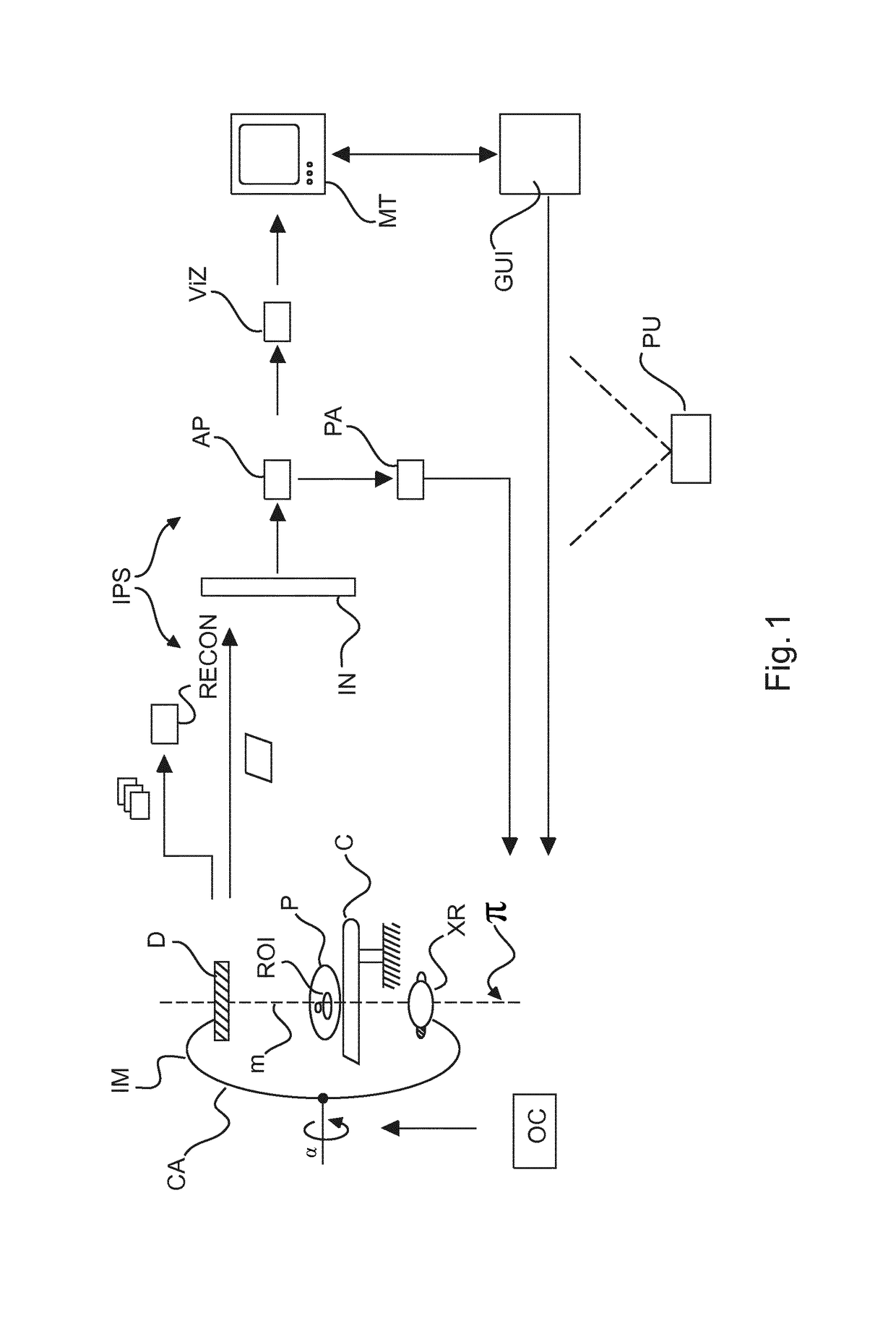
[0033]With reference to FIG. 1, there is shown a schematic block diagram of an imaging arrangement including an imaging apparatus IM and an image processing system IPS.

[0034]More particularly, the left part of the Figure shows a rotational imaging apparatus IM such as a C-arm system or alternatively a CT scanner. The right part of FIG. 1 shows modules and related circuitry of the image processing system IPS. The image processing system IPS allows manual or automatic operation of the imaging apparatus IM so as to reduce effects of streak artifacts in imagery reconstructed from projection data acquired by the imaging apparatus IM.

[0035]Turning now first to a brief description of the imaging apparatus IM, this includes an X-ray source XR and a detector D. Being a rotational X-ray system, it is at least the X-ray source XR that is rotatable in a trajectory around an imaging region. The (rotation) plane of the trajectory is shown in FIG. 1 as a dashed line as said plane is understood to ...


PUM


Abstract

An image processing system, comprising an input port (IN) for receiving a projection image of an object. The image is acquired by a rotational image apparatus (IM) at a position on an imaging trajectory in an adjustable rotation plane (π) around an imaging region. An image artifact extent predictor (AP) of the system is configured to predict for said image a projection area of a reconstruction artifact. A visualizer (VIZ) is configured to visualize, on a display unit (MT), said image with a visual indication of the projection area.

Description

FIELD OF THE INVENTION[0001]The invention relates to an image processing system, to an imaging arrangement, to an image processing method, to a computer program element, and to a computer readable medium.BACKGROUND OF THE INVENTION[0002]The presence, during imaging, of a highly radiopaque object (e.g. a metal object) may cause so-called streak artifacts in rotational tomographic imaging. Such artifacts can obscure clinically relevant information. This is a problem for instance in interventional (stent-assisted) coiling procedures: after a (metallic) coil has been placed to treat aneurysms, the metal coil may cause severe streak artifacts in a reconstructed cone-beam CT (CBCT) image, potentially obscuring clinically relevant details, e.g., the stent-vessel wall interface.SUMMARY OF THE INVENTION[0003]There may therefore be a need for a system and method to deal with image artifacts in rotational imaging.[0004]The object of the present invention is solved by the subject matter of the ...

Claims


Application Information

Patent Timeline
IPC IPC(8): G06T11/00A61B5/00A61B6/03A61B6/00
CPCG06T11/005A61B5/742A61B6/032A61B6/4085G06T11/008
Inventor RUIJTERS, DANIEL SIMON ANNAGRUNHAGEN, THIJS
Owner KONINKLJIJKE PHILIPS NV
Why Eureka
Try Eureka