
Interconnect structure

a technology of interconnections and layouts, applied in the direction of electrical equipment, semiconductor devices, semiconductor/solid-state device details, etc., can solve the problems of increasing the adverse impact of rc delay, reducing the ic computing speed and performance, and creating more problems, so as to simplify the routing design of the interconnect structure and improve the mechanical strength of the whole interconnect structur

Active Publication Date: 2018-12-20
UNITED MICROELECTRONICS CORP
View PDF2 Cites 0 Cited by
  • Summary
  • Abstract
  • Description
  • Claims
  • Application Information

AI Technical Summary

Benefits of technology

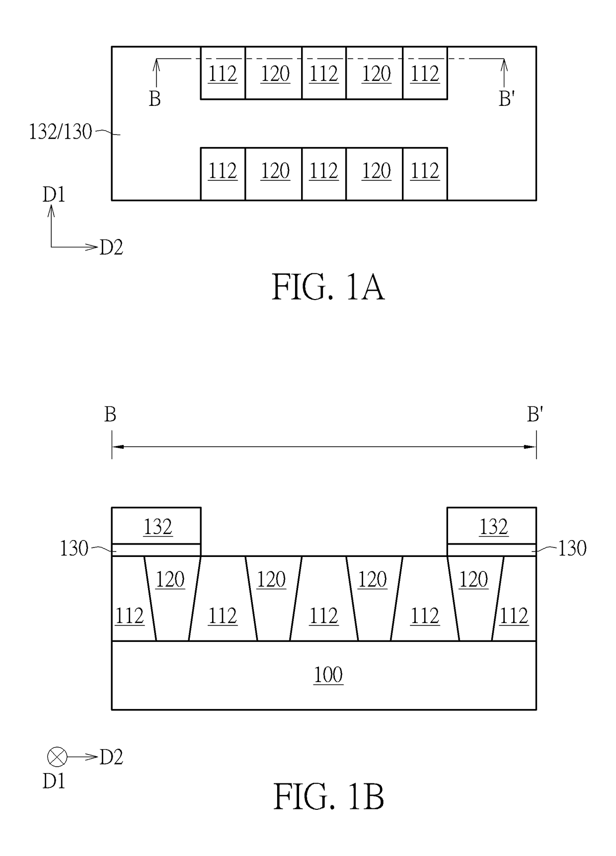
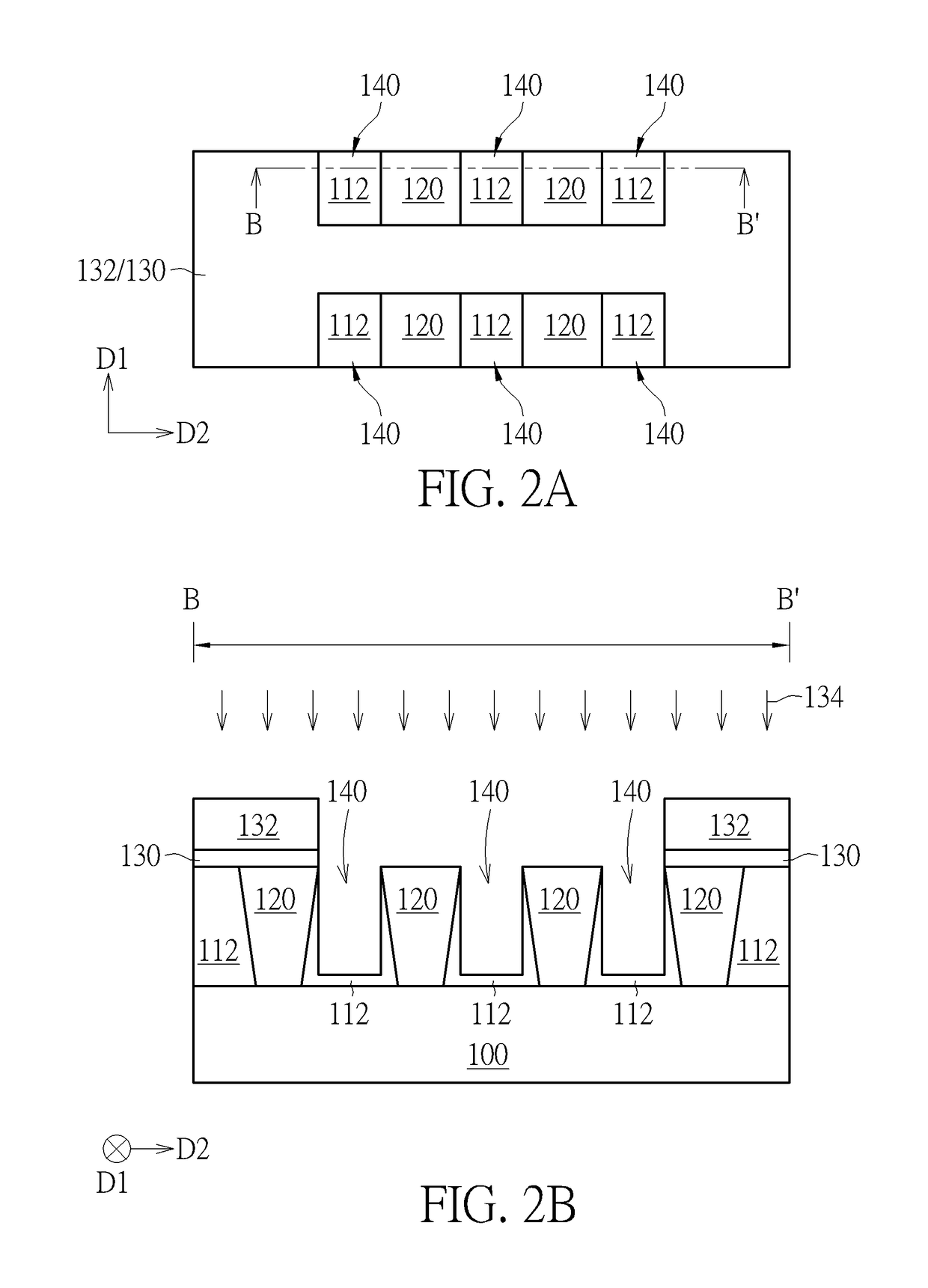
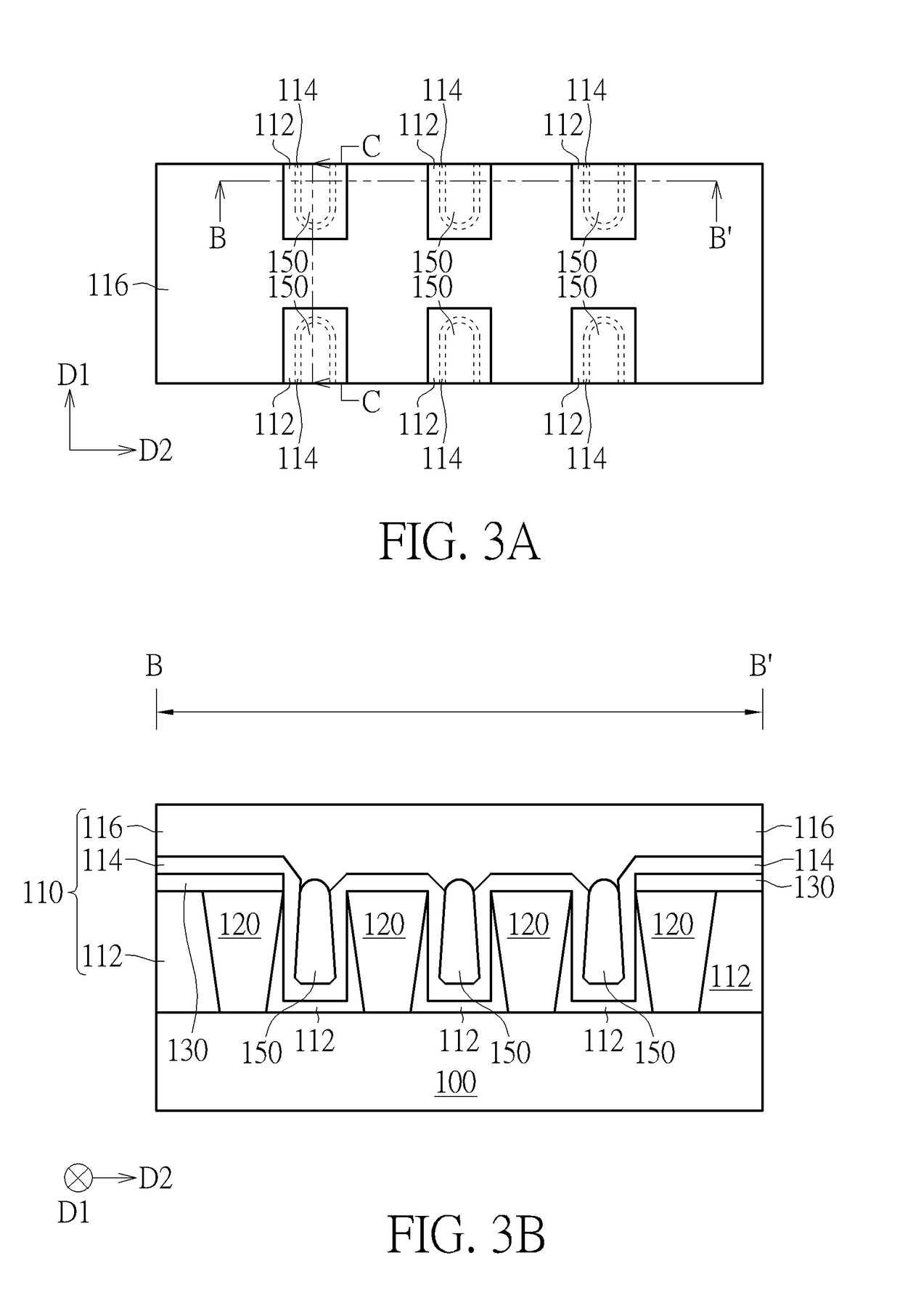
[0009]According to the interconnect structure with air gaps, the interconnect layout structure with air gaps, and manufacturing method thereof provided by the present invention, at least an interconnect unit including the conductive line, the landing mark, and the via structure is provided. The interconnect unit is inserted into and arranged in the interconnect structure and / or the interconnect layout structure depending on different product requirements, and the landing mark of the interconnect unit physically separates the air gaps arranged in a straight line from each other. And the interconnect unit(s) inserted into the interconnect structure with air gaps and the interconnect layout structure with air gaps provides structural support. Consequently, the mechanical strength of the whole interconnect structure is improved. Furthermore, since the interconnect unit can be introduced into the interconnect structure at where it is required, the present invention further simplifies routing design for the interconnect structure.

Problems solved by technology

Consequently, more issues are created because of such reductions.
RC delay unwantedly lowers IC computing speed and performance.
Moreover, abovementioned adverse impact from RC delay is increased when the line width of the ICs is smaller than 0.15 and / or 0.13 micrometer (μm).
Although the formation of air gaps reduces the parasitic capacitance, the conventional process suffers from other drawbacks.
For example, air gap is not strong enough to support the conductive lines and thus reliability issue is generated.
Furthermore, the formation of air gaps is a complicated processing and cannot be made in a mass production.

Method used


Image

  • Interconnect structure
  • Interconnect structure
  • Interconnect structure

Examples


Embodiment Construction

[0024]In the following description, numerous specific details are set forth, such as particular structures, components, materials, dimensions, processing steps and techniques, in order to provide a thorough understanding of the present invention. However, it will be appreciated by one of ordinary skill in the art that the invention maybe practiced without these specific details. In other instances, well-known structures or processing steps have been described in detail in order to avoid obscuring the invention.

[0025]It will be understood that when an element is referred to as being “formed” on another element, it can be directly or indirectly, formed on the given element by growth, deposition, etch, attach, connect, or couple. And it will be understood that when an elements or a layer is referred to as being “on”, “connected to”, or “coupled to” another element or layer, it can be directly on, connected or coupled to the other element or layer or intervening elements or layers may b...


PUM


Abstract

An interconnect layout structure, having a plurality of air gaps, includes a substrate having an insulating material disposed thereon and a conductive line disposed in the insulating material and extending along a first direction. The air gaps are formed in the insulating material and are arranged end-to-end along the first direction and immediately adjacent to a same side of the conductive line. A patterned hard mask is disposed on the conductive line and has a sidewall extending along a second direction that is perpendicular to the first direction and passing between the adjacent air gaps from the top view. A via structure is formed on the conductive line and is electrically connected to the conductive line.

Description

CROSS REFERENCE TO RELATED APPLICATIONS[0001]This application is a continuation of application Ser. No. 15 / 007,212 filed on Jan. 27, 2016, entitled “INTERCONNECT STRUCTURE, INTERCONNECT LAYOUT STRUCTURE, AND MANUFACTURING METHOD THEREOF”, and the entire content of which is hereby incorporated by reference.BACKGROUND OF THE INVENTION1. Field of the Invention[0002]The present invention relates to an interconnect structure, an interconnect layout structure, and a manufacturing method thereof, and more particularly, to an interconnect structure with air gaps, an interconnect layout structure with air gaps and manufacturing method thereof.2. Description of the Prior Art[0003]As the semiconductor industry introduced new generations of integrated circuits (hereinafter abbreviated as ICs) having higher performance and more functionalilty, the density of elements forming the ICs is increased, while the size of the semiconductor devices and line width of the interconnect structures concurrent...

Claims


Application Information

Patent Timeline
Patent Type & Authority Applications(United States)
IPC IPC(8): H01L21/768H01L23/532H01L23/522H01L23/485
CPCH01L23/5222H01L23/485H01L21/7682H01L23/5226H01L23/53295H01L23/535
Inventor CHEN, TONG-YULIN, CHIA-FANG
Owner UNITED MICROELECTRONICS CORP
Learn More