Switching power supply device

a power supply device and switching technology, applied in the direction of electric variable regulation, process and machine control, instruments, etc., can solve the problems of increasing the cost of the switching power supply device accordingly, the dc-dc converter is not successfully started, and it is difficult to reduce the size or weight of the switching power supply devi

Active Publication Date: 2018-12-20
FUJI ELECTRIC CO LTD
View PDF0 Cites 7 Cited by
  • Summary
  • Abstract
  • Description
  • Claims
  • Application Information

AI Technical Summary

Benefits of technology

[0008]As described above, when the first control IC is started, the first control IC drives the PFC circuit. In this operation, the charging voltage of a capacitor connected to the first power supply node is used for the control power supply of the first control IC. However, since the charging voltage alone is not sufficient as the control power supply of the first control IC, the PFC circuit includes an auxiliary winding, which is inductively coupled to an inductor included in the PFC circuit. More specifically, by using power generated across the auxiliary winding when the PFC circuit performs a switching operation, the switching power supply device complements the insufficient power.

Problems solved by technology

This is because, if the DC-DC converter starts before the intermediate voltage is sufficiently boosted, the DC-DC converter is not successfully started.
However, since the charging voltage alone is not sufficient as the control power supply of the first control IC, the PFC circuit includes an auxiliary winding, which is inductively coupled to an inductor included in the PFC circuit.
However, with this switching power supply device according to Japanese Laid-open Patent Publication No. 2015-219946, when the first control IC is started, the insufficiency of the control power supply is supplemented with the power generated across the auxiliary winding coupled to the inductor.
Thus, since the auxiliary winding and a rectifying and smoothing circuit are needed, the cost of the switching power supply device is increased accordingly.
In addition, since space for arranging the auxiliary winding and the rectifying and smoothing circuit is needed, it is difficult to reduce the size or the weight of the switching power supply device.
Thus, if the second control IC is provided with an overvoltage protection function of determining whether the secondary side output voltage of the transformer is in an overvoltage state, the charging voltage across the capacitor connected to the second power supply node is not usable for the overvoltage detection.
However, since the voltage generated across the auxiliary winding coupled to the inductor is added to the voltage supplied from the auxiliary winding of the transformer, the secondary-side output voltage of the transformer is not predictable on the primary side of the transformer.
Consequently, the cost is increased by the configuration of the overvoltage detection circuit and the feedback circuit.

Method used


Image

  • Switching power supply device
  • Switching power supply device
  • Switching power supply device

Examples


Embodiment Construction

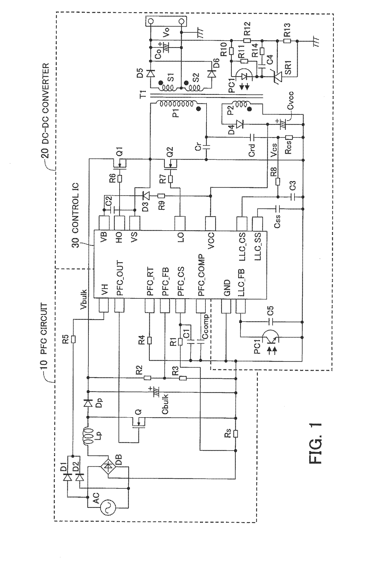
[0025]An embodiment will be described in detail with reference to the drawings by using, as an example, a switching power supply device including a power factor correction (PFC) circuit that operates in a critical current mode in which the PFC circuit sets a switching element to be on after a current that flows through an inductor reaches zero and an LLC current resonance DC-DC converter. In the following description, the name of an individual terminal and a voltage, signal, etc. at that terminal will be denoted by the same reference character, as needed.

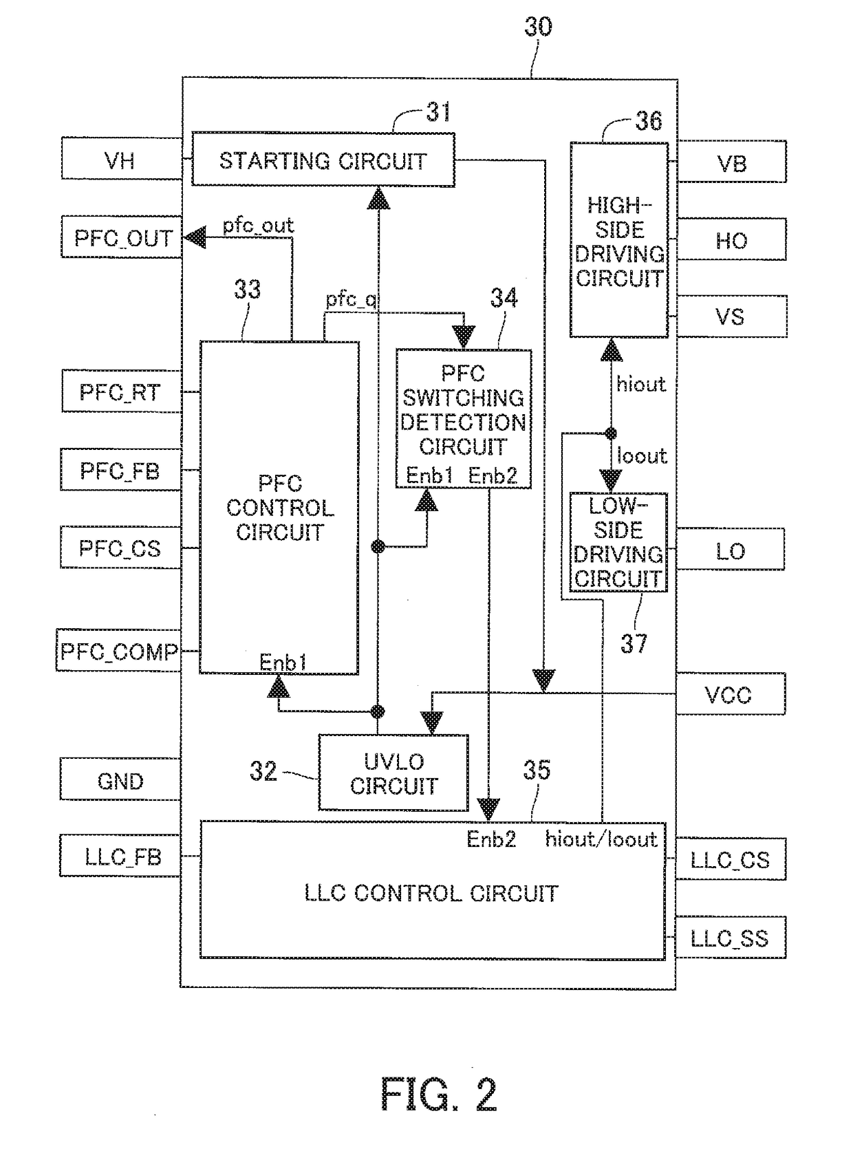
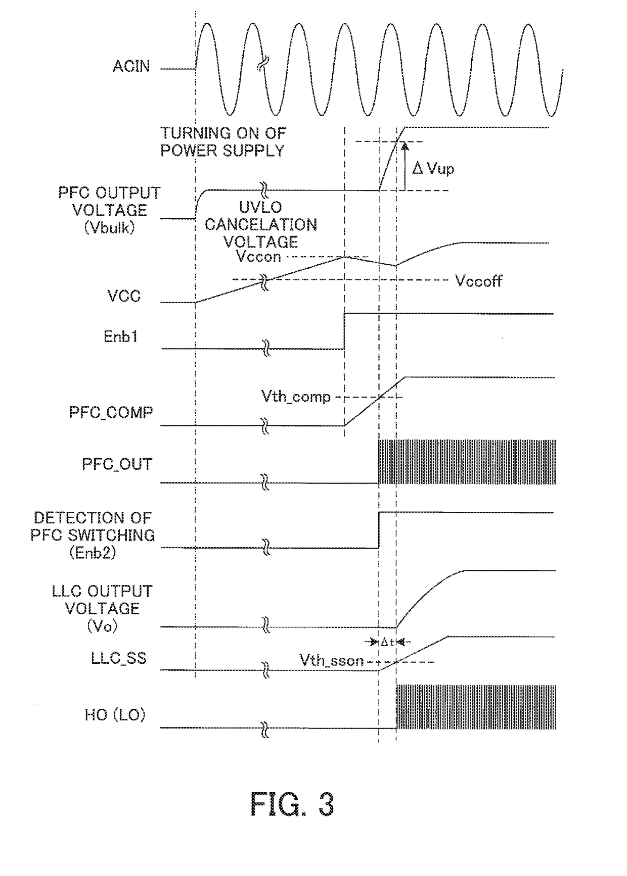
[0026]FIG. 1 is a circuit diagram illustrating a configuration example of a switching power supply device according to one embodiment. FIG. 2 is a functional block diagram illustrating a configuration example of a control IC. FIG. 3 illustrates operation waveforms of the switching power supply device according to one embodiment.

[0027]As illustrated in FIG. 1, the switching power supply device according to the present embodiment incl...


PUM


Abstract

A switching power supply device includes a power factor correction (PFC) circuit, a DC-DC converter, and a control IC incorporating functions of controlling these components. At power up, a capacitor connected to a terminal VCC is charged with a current whose voltage has been adjusted by a starting circuit. When a voltage across the capacitor reaches a UVLO cancelation voltage, an under-voltage lockout (UVLO) circuit outputs a first enable signal, thereby driving a PFC control circuit. When the PFC control circuit outputs a PFC switching signal, a PFC switching detection circuit outputs a second enable signal, thereby driving an LLC control circuit. Since the time between the start of the PFC switching operation and the start of the operation of the LLC control circuit is shortest, there is no need to supplement the starting power and arrange an auxiliary winding for an inductor.

Description

CROSS-REFERENCE TO RELATED APPLICATION[0001]This application is based upon and claims the benefit of priority of the prior Japanese Patent Application No. 2017-116471, filed on Jun. 14, 2017, the entire contents of which are incorporated herein by reference.BACKGROUND OF THE INVENTION1. Field of the Invention[0002]Embodiments discussed herein relate to a two-stage switching power supply device including an upstream power factor correction (PFC) circuit and a downstream direct-current (DC)-DC converter cascaded to the PFC circuit. The switching power supply device generates a DC output voltage from an alternating-current (AC) power supply.2. Background of the Related Art[0003]This kind of two-stage switching power supply device including an upstream PFC circuit and a downstream DC-DC converter is used for a power supply device used for home appliances that include lighting power supply circuits or whose power consumption is 75 watts (W) or more. The PFC circuit improves the power fac...

Claims


Application Information

Patent Timeline
Patent Type & Authority Applications(United States)
IPC IPC(8): H02M1/36H02M1/42H02M3/335H02M1/32
CPCH02M1/36H02M1/4225H02M2001/0009H02M1/32H02M3/33569H02H7/1213H02M1/4208H02M3/01H02M3/33571Y02B70/10H02M1/0058H02M1/007H02M1/0009
Inventor MARUYAMA, HIROSHI
Owner FUJI ELECTRIC CO LTD
Why Eureka
Try Eureka