LED driver

a technology of led drivers and projection arrangements, applied in the direction of optics, instruments, semiconductor lamp usage, etc., can solve the problems of reducing the quality of viewing experience, overshooting (or undershooting) of light output, and effectively wasteing ligh

Active Publication Date: 2020-01-21
SIGNIFY HLDG BV
View PDF18 Cites 0 Cited by
  • Summary
  • Abstract
  • Description
  • Claims
  • Application Information

AI Technical Summary

Benefits of technology

[0009]In the LED driver according to the invention, the control means generates the gate signal for the load switch such that a transition of this load switch gate signal is delayed relative to a corresponding transition of the gate signal for the converter switch. An advantage of the LED driver according to the invention is that, by this approach to the gate signal timing, an overshoot on the LED current can be effectively eliminated or at least reduced to a level that will not result in noticeable behavior on the light output. The LED arrangement can therefore be switched from “off” to “on” with a greater degree of precision, with a minimum time interval until the LED is stable at the desired intensity.
[0011]An advantage of the projection arrangement according to the invention is that the higher precision in the light output owing to the control signal timing of the inventive LED driver leads to an improvement in the quality in the viewing experience. Images can be projected with more accuracy, without the aliasing that can be perceived in comparable projection arrangements that use prior art LED drivers. A further advantage is an increase in efficiency and brightness. In a projection arrangement according to the invention, the micro-mirrors do not have to be timed to allow for an overshoot / undershoot. Minimizing the time interval until the LED is stable at the desired intensity improves the overall efficiency.
[0013]The method according to the invention is relatively straightforward to realize, while delivering a noticeable improvement in the behavior of the LEDs at the critical transitions between inactive and active phases.
[0020]The energy transfer to the capacitor at the end of the active phase, and its subsequent release through the load at the beginning of the next active phase is the reason for the noticeable overshoot on the LED current when the load is driven using the known LED driver arrangements, i.e. with simultaneous leading edges of the gate signals. This in turn results in a corresponding overshoot / undershoot on the light output. In the LED driver according to the invention, the strobe signal timing is adjusted to alter the energy transfer so that, at the beginning of an active phase, the capacitor voltage is neither too high nor too low, essentially eliminating an overshoot / undershoot on the LED current and light output. To this end, in a preferred embodiment of the invention, the control means is realized to time the transitions of the strobe signal relative to the converter switch gate signal according to energy stored in the energy storage elements.
[0030]The effect of applying this inductor current offset (whether using a predetermined value or a measured value for the threshold current) is that, after the final converter switch gate pulse, the power converter is turned “off”, but the LED load continues to draw current. This has the effect that some of the stored energy is transferred into the LED load, thus preventing the capacitor voltage from reaching an undesirably high level, with the result that less “excess energy” can remain in the capacitor to discharge into the load at the beginning of the next active phase. Effectively, the invention is to achieve an improved energy balance at the beginning and / or end of an active phase. For example, in the case of a boost converter, there is no current delivered to the load when the inductor current is increasing, so the best time to turn on the converter switch is when the capacitor voltage is close to the minimum voltage it would have during continuous mode operation. Since the capacitor voltage would generally be higher than this level (on account of the energy transfer at the previous active phase, as explained above), turning on the converter switch earlier than the load switch allows the capacitor to discharge slightly. In the case of a buck converter, current is always delivered to the capacitor, however at the start of an active phase, it is inadequate the power the LED arrangement and would therefore lead to undershoot. Therefore, with a buck converter, the best time to turn on the load switch is when the inductor current reaches the minimum it would during continuous mode operation, adjusted if necessary to account for extra energy in the capacitor.

Problems solved by technology

However, this can result in a noticeable overshoot (or undershoot) on the LED current, which in turn leads to an overshoot (or undershoot) on the light output.
Excess light as a result of an overshoot can be perceived by a viewer, thus detracting from the quality of the viewing experience.
However, some light is effectively wasted, leading to a reduction in the overall efficiency and brightness.

Method used


Image

  • LED driver
  • LED driver
  • LED driver

Examples


Embodiment Construction

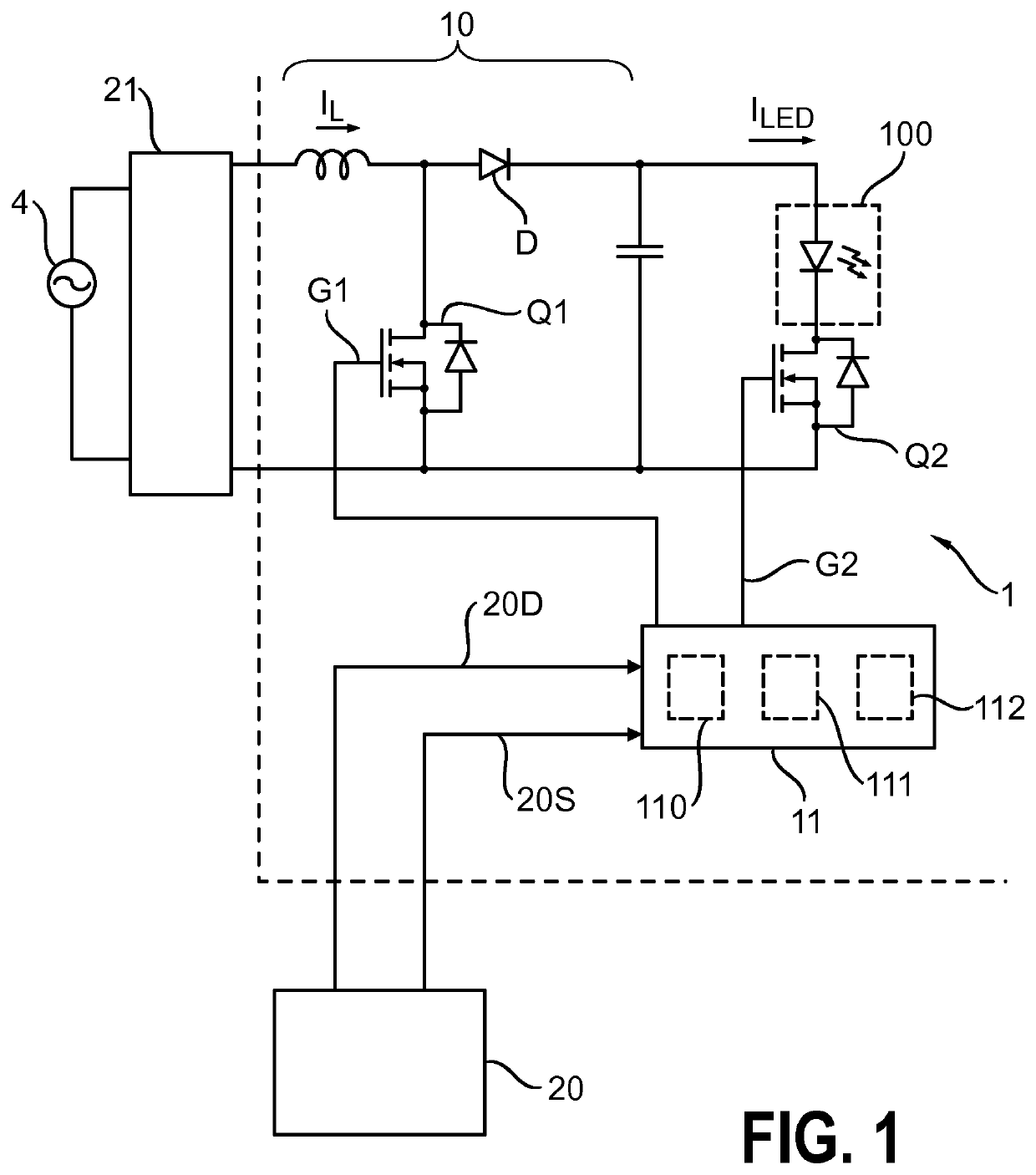
[0040]FIG. 1 shows a simplified block diagram of an LED driver 1 according to an embodiment of the invention. The LED driver 1 is realized to drive an LED lighting load 100 that can comprise any appropriate number and arrangement of LEDs, and is shown in relationship to a processor 20 and power converter 21 of a DLP system. The DLP processor 20 issues a dim level 20D and a strobe request 20S to the LED driver 1. The strobe request 20S is used to regulate the “on time” of the LEDs, while the dim level 20D is used to regulate the light intensity in the projected image. Here, the LED driver 1 comprises a boost converter 10 that is provided with a rectified input from a power converter 40 driven from a mains power supply 4. The boost converter 10 comprises a known arrangement of inductor L, diode D, capacitor C, and semiconductor switch Q1, referred to as the “converter switch” in the following. In this embodiment, the switch Q1 is a MOSFET. A second semiconductor switch Q2 is arranged ...


PUM

PropertyMeasurementUnit
currentaaaaaaaaaa
current levelaaaaaaaaaa
energy transferaaaaaaaaaa

Abstract

LED driver (1) comprising a switched-mode power converter (10) for providing power to an LED arrangement (100) connected across output terminals of the converter (10), and wherein the converter (10) comprises a number of energy storage elements (L, C) and a first semiconductor switch (Q1); a second semiconductor switch (Q2) connected in series with the LED arrangement (100); a control means (11) realized to generate a second control signal (G2) for the second semiconductor switch (Q2), such that a transition of the second control signal (G2) is delayed relative to a corresponding transition of a first control signal (G 1) for the first semiconductor switch (Q 1). The invention further describes a projection arrangement (2); and a method of driving an LED arrangement (100).

Description

CROSS-REFERENCE TO PRIOR APPLICATIONS[0001]This application is the U.S. National Phase application under 35 U.S.C. § 371 of International Application No. PCT / EP2016 / 053587, filed on Feb. 19, 2016 which claims the benefit of European Patent Application No. 15158219.4, filed on Mar. 9, 2015. These applications are hereby incorporated by reference herein.FIELD OF THE INVENTION[0002]The invention describes an LED driver, a projection arrangement, and a method of driving an LED arrangement.BACKGROUND OF THE INVENTION[0003]In a digital light processing (DLP) device that uses a micro-mirror array to cast an image onto a screen, an arrangement of high-power light-emitting diodes (LEDs) can be used as a light source. Apart from their favorably long life-time, an advantage of using LEDs is that they can be switched on and off at very high switching frequencies. Furthermore, the light output essentially follows the current though the LEDs, so that the light output is also characterized by favo...

Claims


Application Information

Patent Timeline
Patent Type & Authority Patents(United States)
IPC IPC(8): H05B33/08H02M1/00G03B21/00G03B21/20H05B44/00
CPCG03B21/2053H05B45/50H05B47/16H05B45/37H05B45/10H05B45/44H05B45/38H02M2001/007G03B21/008G03B21/2013G03B21/2033Y02B20/346Y02B20/30H05B45/3725H02M1/007
Inventor RUTGERS, ANDREW ULRICH
Owner SIGNIFY HLDG BV
Why Eureka
Try Eureka