Hydraulic control system for vehicle

a technology of hydraulic control system and vehicle, which is applied in the direction of mechanical equipment, machines/engines, transportation and packaging, etc., can solve the problems of insufficient power of electric motor that drives it is not possible to appropriately start up the electric oil pump, so as to prevent the occurrence of secondary failure and reduce the excessive consumption of electric power

Active Publication Date: 2018-01-09
TOYOTA JIDOSHA KK
View PDF29 Cites 1 Cited by
  • Summary
  • Abstract
  • Description
  • Claims
  • Application Information

AI Technical Summary

Benefits of technology

[0011]This application is directed to a hydraulic control system including the above-described mechanical oil pump and electric oil pump. This application provides a hydraulic control system for a vehicle, which is able to improve the startability of the electric oil pump without leading to the complexity of the system, an increase in size, an increase in cost, or the like.
[0013]The hydraulic control system includes the third oil passage that communicates the mechanical oil pump with the electric oil pump. For example, the throttle mechanism, such as an orifice and a throttle valve, is provided in the third oil passage. Therefore, by driving the mechanical oil pump at the time of starting up the electric oil pump, it is possible to flow oil, which is discharged from the mechanical oil pump, back to the electric oil pump side and transfer the oil to the electric oil pump side. For example, in a state where the viscosity of oil is high at a low temperature, the power of the electric motor that drives the electric oil pump may be insufficient, and it may not be possible to appropriately start up the electric oil pump. In contrast, in this invention, at the time of starting up the electric oil pump as described above, it is possible to forcibly flow oil back to the electric oil pump side with the use of the mechanical oil pump having a larger power than the electric oil pump. Therefore, it is possible to transfer relatively high-temperature oil around the mechanical oil pump to the electric oil pump side. Alternatively, it is possible to transfer low-viscosity oil to the electric oil pump side by forcibly feeding the oil under pressure with the use of the mechanical oil pump. Therefore, it is possible to reduce load on the electric motor at the time of starting up the electric oil pump, so it is possible to improve the startability of the electric oil pump.
[0015]When the mechanical oil pump is driven at the time of starting up the electric oil pump as described above, for example, it is possible to drive the mechanical oil pump together with the crankshaft of the engine by starting up the engine to rotate the crankshaft. Alternatively, by not operating the engine through combustion but motoring the engine to rotate the crankshaft, it is possible to drive the mechanical oil pump. It is possible to easily flow oil, which is discharged from the mechanical oil pump by hydraulic pressure generated by driving the mechanical oil pump, back to the electric oil pump side.
[0019]As described above, the hydraulic control system determines whether driving of the electric oil pump is allowed, allows the electric oil pump to be driven, and then starts driving the electric oil pump. At this time, it is determined whether there is a failure associated with the electric oil pump on the basis of the rotation speed of the electric oil pump. That is, when the rotation speed of the electric oil pump does not reach the predetermined rotation speed although driving of the electric oil pump is allowed and the driving is started, it is determined that there is a failure in the electric oil pump or in the structure associated with the electric oil pump. Therefore, in this case, driving of the electric oil pump is suppressed, which includes the case where driving of the electric oil pump is stopped. Therefore, when there occurs a failure, it is possible to suppress excessive consumption of electric power at the time when the electric oil pump is driven. It is also possible to prevent occurrence of a secondary failure due to the fact that the electric oil pump is continuously driven in a state where there is a failure.

Problems solved by technology

For example, in a state where the viscosity of oil is high at a low temperature, the power of the electric motor that drives the electric oil pump may be insufficient, and it may not be possible to appropriately start up the electric oil pump.

Method used


Image

  • Hydraulic control system for vehicle
  • Hydraulic control system for vehicle
  • Hydraulic control system for vehicle

Examples


Embodiment Construction

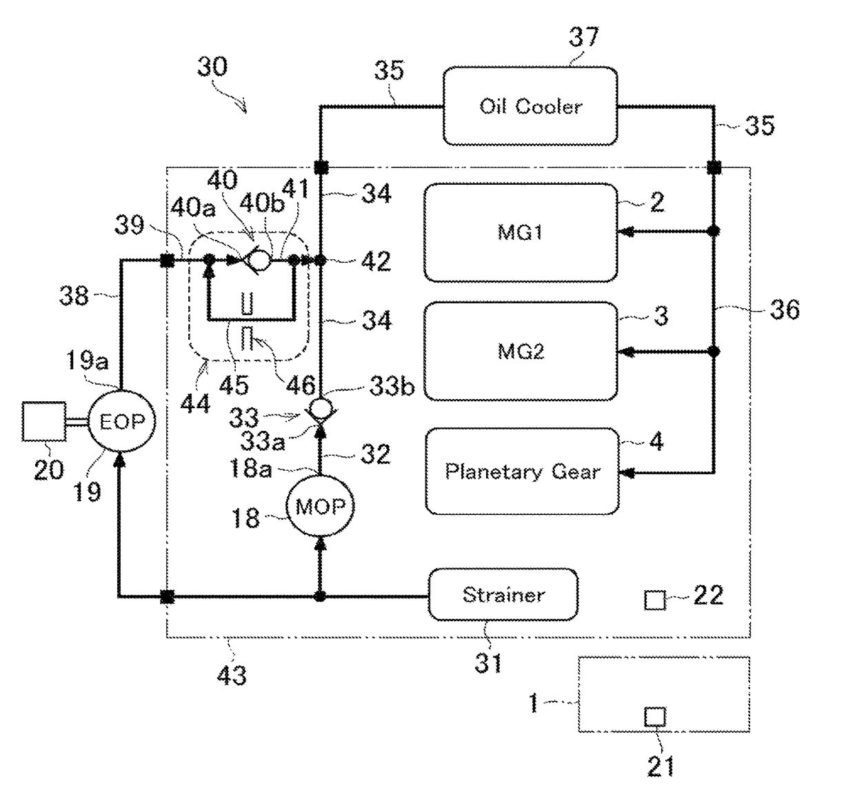
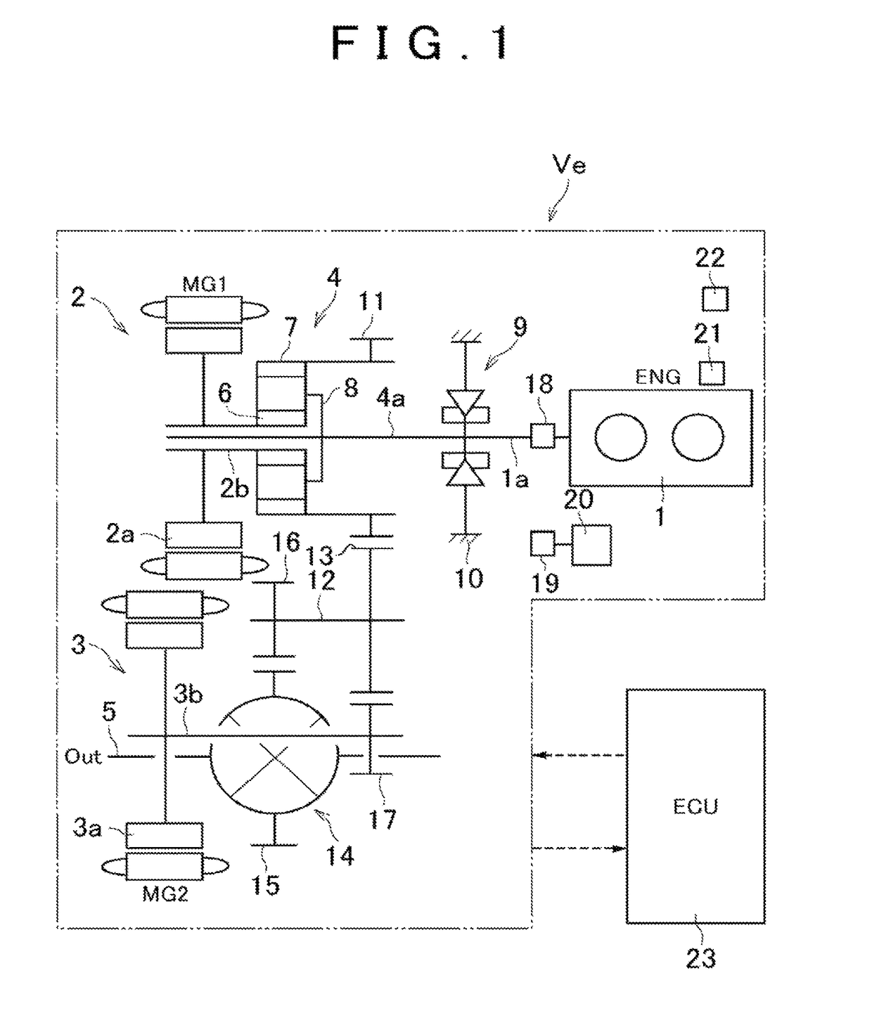
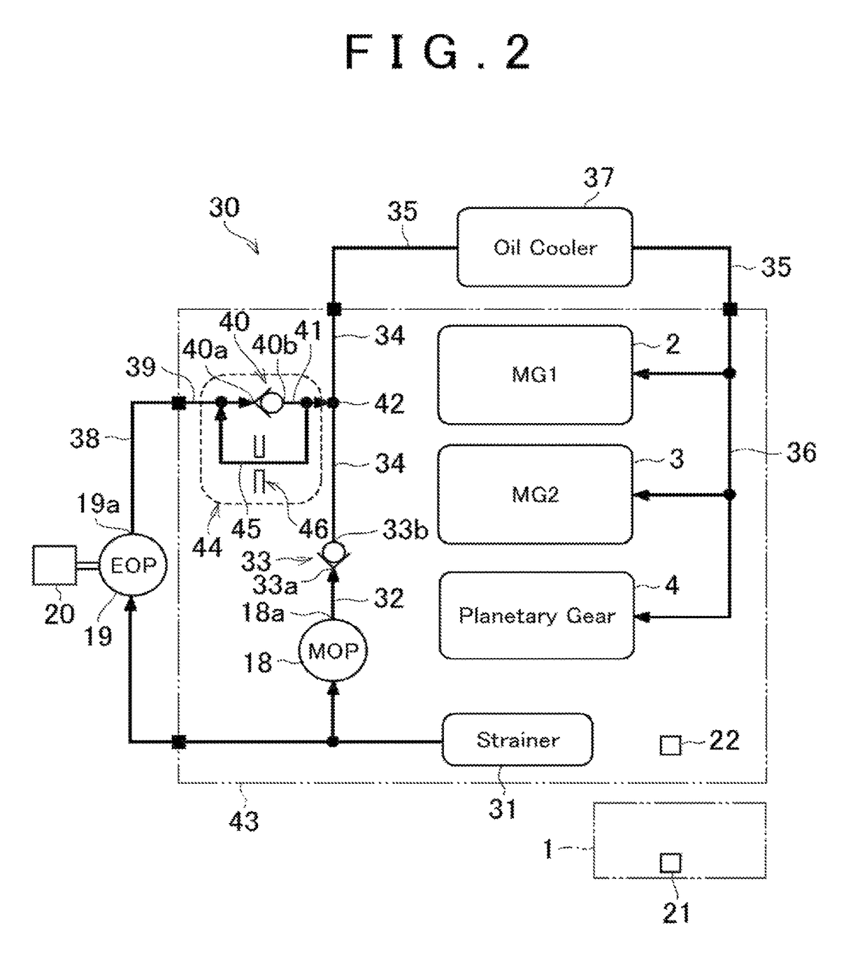
[0026]An embodiment of the invention will be specifically described with reference to the accompanying drawings. Initially, FIG. 1 shows an example of a vehicle that may be a subject of the invention. The vehicle that is a subject of the invention, as will be described later, includes a mechanical oil pump and an electric oil pump. The mechanical oil pump is driven by a driving force source of the vehicle to generate hydraulic pressure. The electric oil pump is driven by an electric motor, different from the driving force source of the vehicle, to generate hydraulic pressure. The vehicle is configured to, when the vehicle temporarily stops the operation of the driving force source while the vehicle is traveling or the vehicle is temporarily stopped, keep supplying oil by driving the electric oil pump. The vehicle that temporarily stops the operation of the driving force source while the vehicle is traveling or the vehicle is temporarily stopped includes, for example, a vehicle equip...


PUM


Abstract

A first check valve of a hydraulic control system allows oil to flow in only a direction from a first oil pump toward an oil receiving portion. A second check valve allows oil to flow in only a direction from a second oil pump toward the oil receiving portion. A third oil passage is configured to provide communication between a merging point of a first oil passage and a second oil passage, and the second oil pump by bypassing the second check valve. The third oil passage includes a throttle mechanism. The third oil passage is configured to restrict a flow rate of oil that is discharged from the second oil pump.

Description

INCORPORATION BY REFERENCE[0001]The disclosure of Japanese Patent Application No. 2014-187823 filed on Sep. 16, 2014 including the specification, drawings and abstract is incorporated herein by reference in its entirety.BACKGROUND OF THE INVENTION[0002]1. Field of the Invention[0003]The invention relates to a hydraulic control system for a vehicle, the hydraulic control system including a mechanical oil pump that is driven by a driving force source for the vehicle, such as an engine and a motor, and an electric oil pump that is driven by an electric motor different from the driving force source.[0004]2. Description of Related Art[0005]Japanese Patent Application Publication No. 2013-142458 (JP 2013-142458 A) describes the invention regarding an oil supply system including a mechanical oil pump and an electric oil pump as pumps for supplying oil. The oil supply system described in JP 2013-142458 A includes an electromagnetic valve as changing means for changing a communication state ...

Claims


Application Information

Patent Timeline
Patent Type & Authority Patents(United States)
IPC IPC(8): F01M1/16F01M5/00F01M1/18F16H61/02F16H61/00F01M1/02F16H61/12
CPCF01M1/16F01M1/02F01M1/18F01M5/005F16H61/0206F16H61/0031Y10S903/904F01M2001/0215F01M2001/0269F16H61/0009F16H61/0025F16H2061/1208B60K6/445B60K6/40B60W2510/107Y02T10/62B60K6/20B60K17/356F16H61/12
Inventor KODAMA, TAKUYAKIMURA, HIROAKIINAOKA, SHIGEHO
Owner TOYOTA JIDOSHA KK
Why Eureka
Try Eureka