
Ignition device for internal combustion engine

a technology of ignition device and internal combustion engine, which is applied in the direction of engine starters, ignition automatic control, electric control, etc., can solve the problems of preventing engine startability and unstable idling, and achieve the effect of improving engine startability

Active Publication Date: 2009-01-06
MAHLE INT GMBH
View PDF2 Cites 17 Cited by
  • Summary
  • Abstract
  • Description
  • Claims
  • Application Information

AI Technical Summary

Benefits of technology

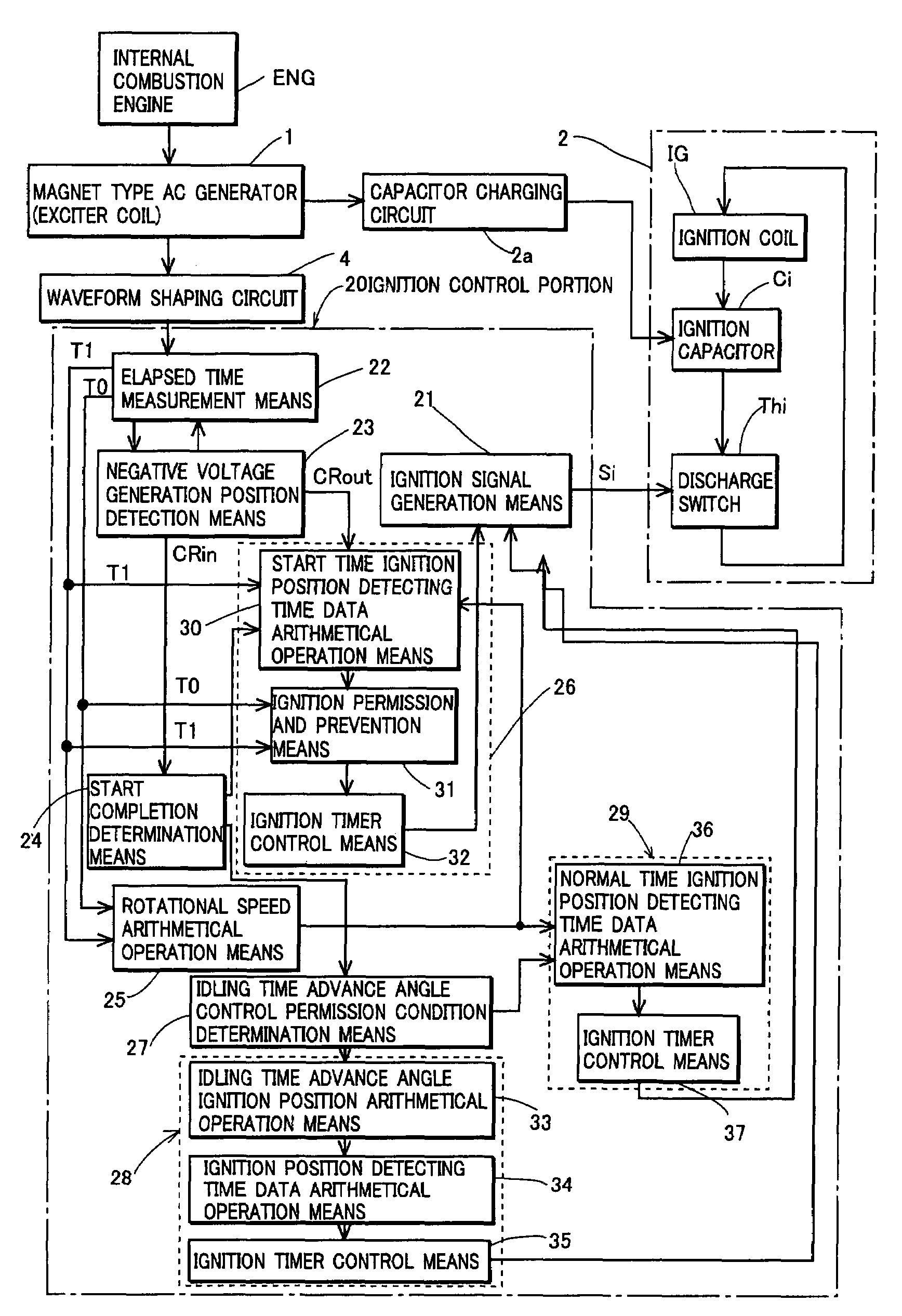
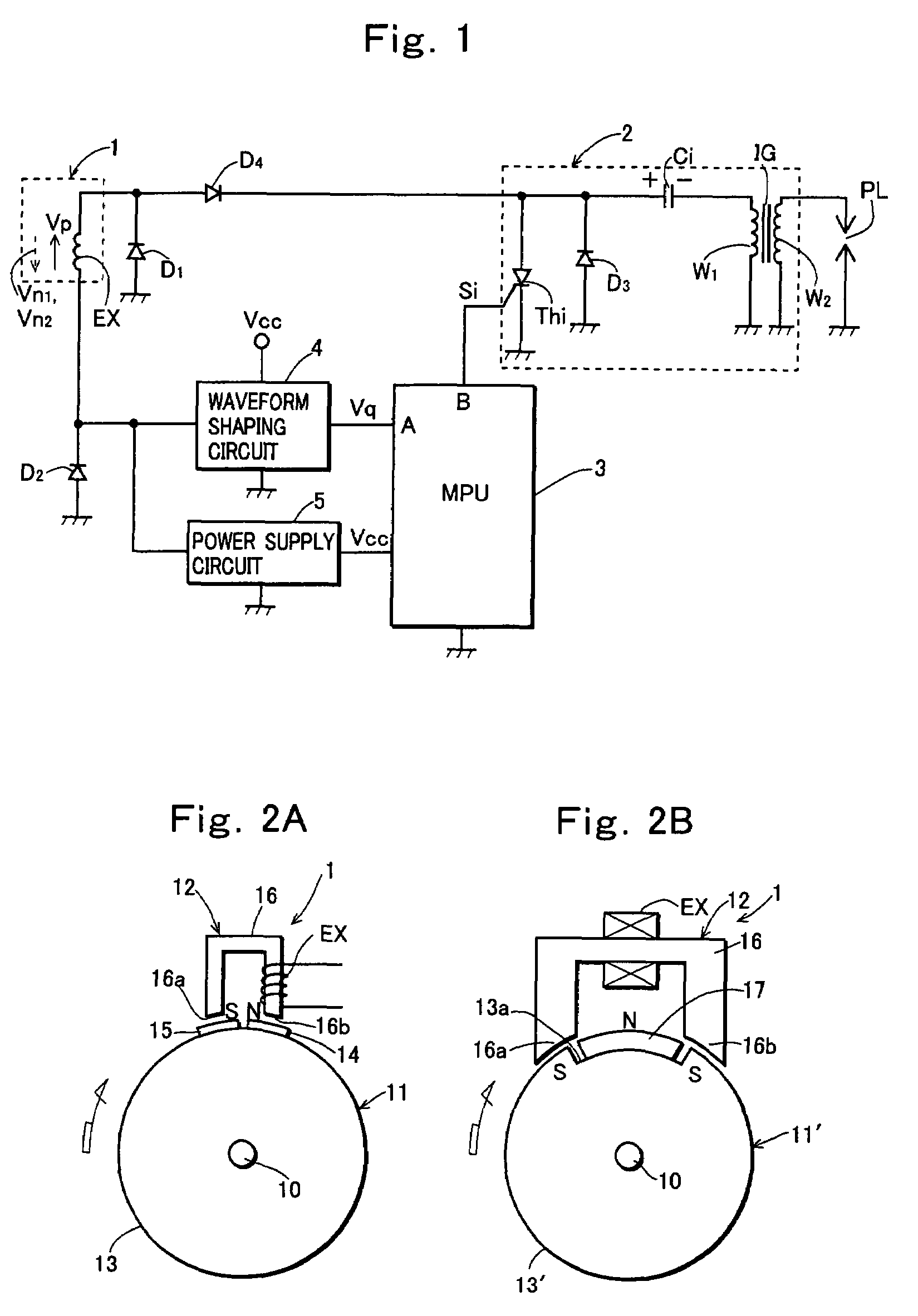
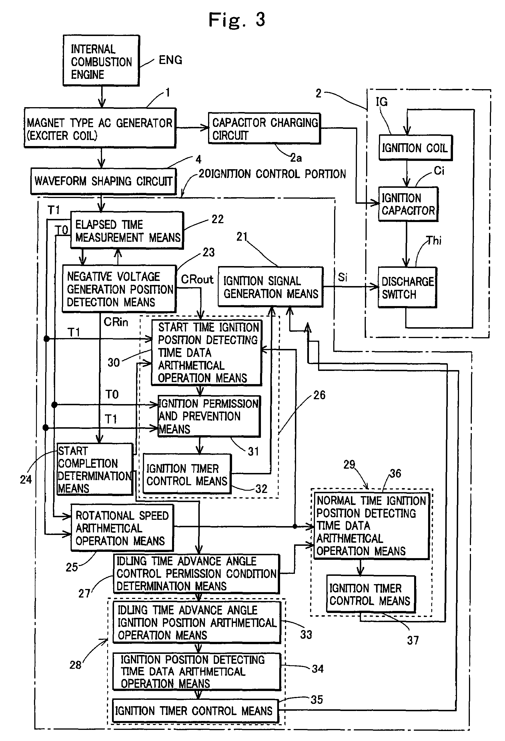
The present invention provides an ignition device for an internal combustion engine that can accurately determine the ignition position at start-up and stabilize idling after start-up in cold climates. The device includes an exciter coil, an ignition control portion, and an idling time advance angle control means. The ignition control portion uses start completion determination and an idling time advance angle control permission condition to set the ignition position at start-up and during idling. The device can improve start-up and stability of the engine, and is applicable to both gas and diesel engines.

Problems solved by technology

However, at the start of the engine, the rotational speed of the crankshaft minutely varies with stroke changes of the engine, and thus when the ignition position detecting time data is calculated based on the rotational speed arithmetically operated from the rotational speed detecting time data measured one turn before of the engine, the ignition position at the start of the engine is improper, thereby inevitably preventing startability of the engine.
However, in the proposed ignition device, since control is shifted to normal control immediately after the internal combustion engine has completed the start, idling is not stabilized until the engine warms up in cold climates.

Method used


Image

  • Ignition device for internal combustion engine
  • Ignition device for internal combustion engine
  • Ignition device for internal combustion engine

Examples


third embodiment

[0158]FIG. 17 shows an algorithm of a CRin processing executed by a microprocessor for each generation of a first negative voltage Vn1 by an exciter coil in the present invention. Algorithms of a processing in powering up, a memory initialization processing, an every 2-msec processing, a crank interruption processing, and a CRout processing performed for each generation of a second negative voltage Vn2 are the same as shown in FIGS. 8, 9, 10, 11 and 13.

[0159]The CRin processing in FIG. 17 is the CRin processing in FIG. 12 with an addition of Step S518. According to the CRin processing in FIG. 17, when it is determined in Step S510 that the present control is idling time advance angle control, it is determined in Step S518 whether a rotational speed of the engine is equal to or higher than an idling time advance angle control determination speed continuously for a set certain period. When it is determined that the period in which the rotational speed of the engine is continuously equ...

first embodiment

[0162]The CRin processing in FIG. 20 is such that Steps S511 and S512 are omitted from the CRin processing in FIG. 17, and when it is determined in Step S518 that the period in which the rotational speed of the engine is continuously equal to or higher than the idling time advance angle control determination speed does not reach the certain period, the process moves to Step S513 where idling time advance angle ignition position detecting time data Tigi is arithmetically operated, and when it is determined in Step S518 that the period in which the rotational speed of the engine is continuously equal to or higher than the idling time advance angle control determination speed reaches the certain period, the process moves to Step S515 where the idling time advance angle control is finished. Other points are the same as in the CRin processing in the

[0163]When the CRin processing is comprised as shown in FIG. 20, idling time advance angle control permission condition determination means 2...

fifth embodiment

[0165]FIGS. 21 and 22 show algorithms of a CRin processing and a CRout processing executed by a microprocessor in the present invention. In the embodiment, algorithms of a processing in powering up, a memory initialization processing, an every 2-msec processing, and a crank interruption processing are the same as in FIGS. 8, 9, 10 and 11. In the embodiment, a generation position of a second negative voltage Vn2 is set in a position advanced from an idling time advance angle ignition position.

[0166]The CRin processing in FIG. 21 is such that Steps S513 and S514 are omitted from the CRin processing in FIG. 12. In the CRin processing in FIG. 21, only Step S511 where a count value Idle_cnt of an idling time advance angle control counter is incremented, and a process of performing idling time advance angle control when the count value Idle_cnt of the idling time advance angle control counter is equal to or smaller than an idling time advance angle control number set value IDLENUM, and fi...


PUM


Abstract

A capacitor discharge ignition device for an internal combustion engine including: idling time advance angle control permission condition determination means for determining whether an idling time advance angle control permission condition is met that is a condition for permitting control to advance an ignition position during idling immediately after completion of the start of the engine in order to stabilize idling immediately after completion of the start of the internal combustion engine; and idling time advance angle control means for advancing the ignition position during idling immediately after completion of the start of the internal combustion engine when it is determined that the idling time advance angle control permission condition is met.

Description

TECHNICAL FIELD OF THE INVENTION[0001]The present invention relates to a capacitor discharge ignition device for an internal combustion engine.PRIOR ART OF THE INVENTION[0002]A capacitor discharge ignition device for an internal combustion engine is comprised of an ignition coil, an ignition capacitor that is provided on a primary side of the ignition coil and charged to one polarity by an output of an ignition power supply, a discharge switch that conducts when receiving an ignition signal and discharges charges accumulated in the ignition capacitor through the primary coil of the ignition coil, and an ignition control portion that provides the ignition signal to the discharge switch in an ignition position of the internal combustion engine. As the ignition power supply, an exciter coil is often used provided in a magnet type AC generator mounted to the engine.[0003]Recent internal combustion engine driven vehicles or internal combustion engine driven devices require complicated co...

Claims


Application Information

Patent Timeline
Patent Type & Authority Patents(United States)
IPC IPC(8): F02P5/00F02N17/00F02P3/05F02D45/00F02N99/00F02P3/08F02P5/15
CPCF02P3/0807F02P5/1506F02P5/1508Y02T10/46Y02T10/40
Inventor NAKAUCHI, KIYOTADASUGIYAMA, MASAYUKIHATANO, YASUKAZUSHIMOYAMA, AKIRA
Owner MAHLE INT GMBH
Learn More