Controller of internal combustion engine

Inactive Publication Date: 2008-08-28
DENSO CORP
View PDF12 Cites 17 Cited by
  • Summary
  • Abstract
  • Description
  • Claims
  • Application Information

AI Technical Summary

Benefits of technology

[0007]It is an object of the present invention to provide a controller of an internal combustion eng

Problems solved by technology

The above-described structure can detect the disconnection of the glow plug but cannot cope with the disconnection when the disconnection actually arises.
That is, when the disconnection arises, there is

Method used


Image

  • Controller of internal combustion engine
  • Controller of internal combustion engine
  • Controller of internal combustion engine

Examples


first embodiment

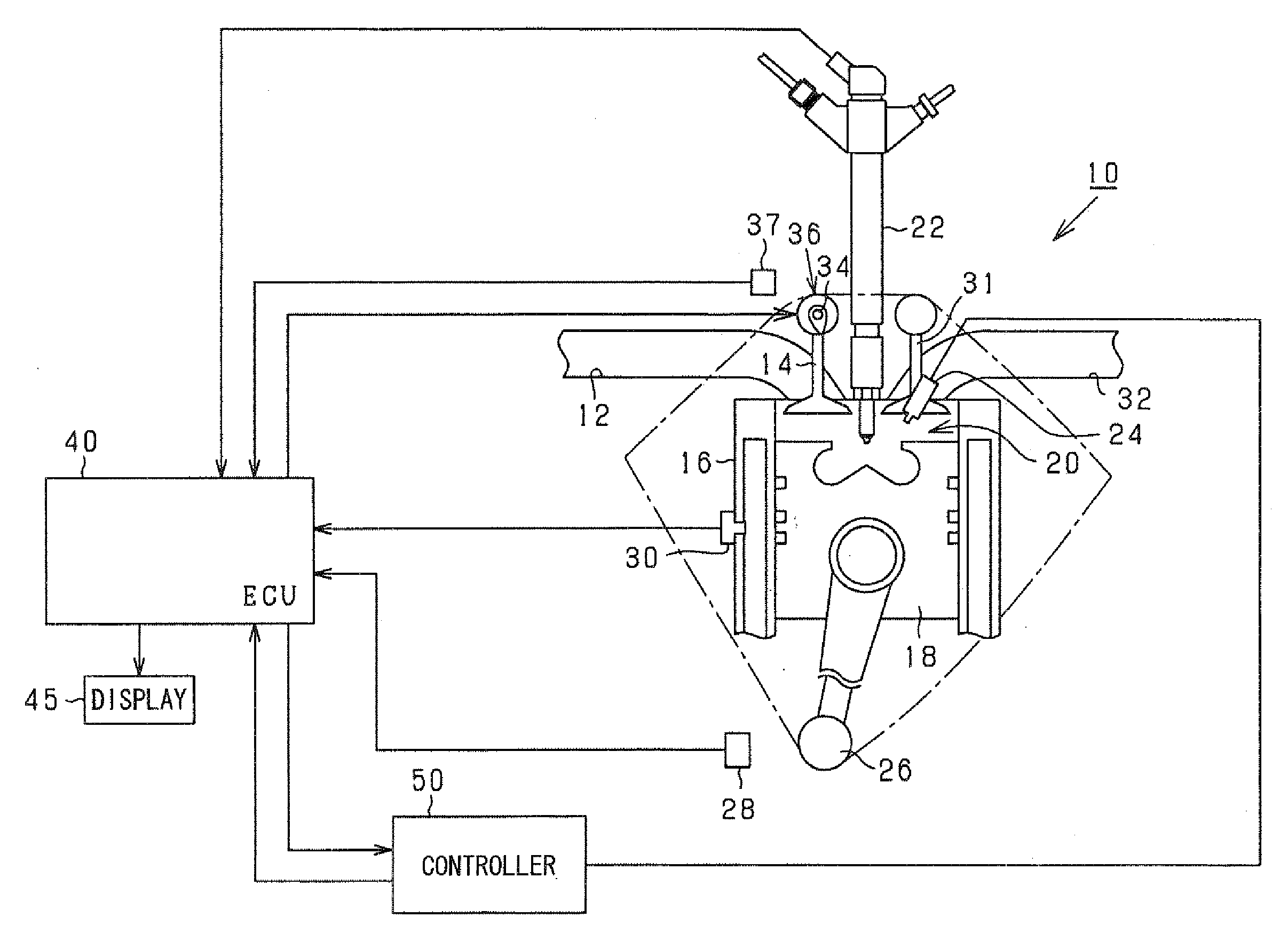
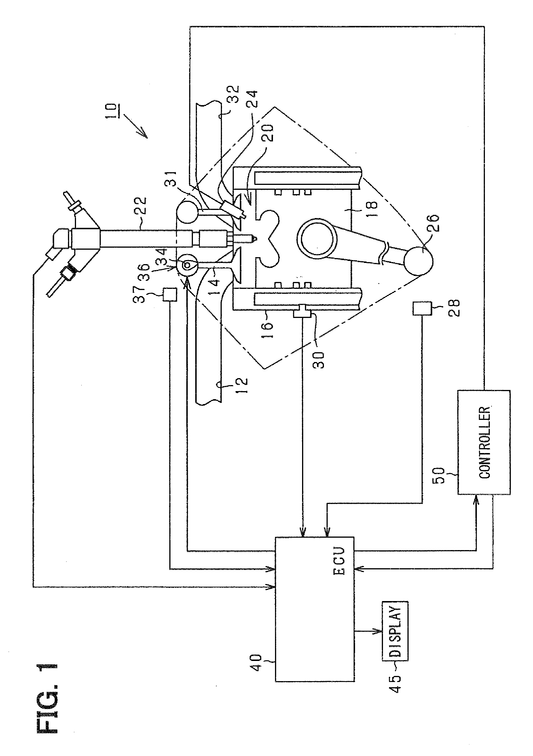
[0023]Referring to FIG. 1, a controller of an internal combustion engine according to the present invention applied to a controller of a vehicular diesel engine is illustrated. FIG. 1 is a structural diagram showing an engine system according to the present embodiment. As shown in FIG. 1 an intake passage 12 of the diesel engine 10 communicates with a combustion chamber 20 by an opening operation of an intake valve 14. The combustion chamber 20 is defined by a cylinder block 16 and a piston 18. A tip end portion of an injector 22 projects into the combustion chamber 20. Thus, injection supply of fuel to the combustion chamber 20 is enabled. A glow plug 24 as a heat generating unit projecting into the combustion chamber 20 is provided in the combustion chamber 20.

[0024]If the fuel is injected into the combustion chamber 20, the fuel causes self-ignition due to compression of the combustion chamber 20, and energy is generated. The energy is taken out as rotational energy of an output ...

second embodiment

[0068]In the above-described first or second embodiment, the four kinds of processing in Steps S54 to S57 of FIG. 9 may be used together as processing from the starter ON state to the completion of the starting. That is, for example, according to the situation, the processing for delaying the valve timing may be used in combination with the processing for increasing the fuel injection quantity of the normal cylinder. For example, according to the situation, the processing for delaying the injection timing of the abnormal cylinder may be used in combination with the processing for increasing the fuel injection quantity of the normal cylinder. For example, according to the situation, the processing for delaying the injection timing of the abnormal cylinder may be used in combination with the processing for delaying the valve timing of the abnormal cylinder. Moreover, for example, according to the situation, the processing for delaying the injection timing of the abnormal cylinder, the...


PUM


Abstract

A glow plug is provided in a combustion chamber of a diesel engine. An ECU diagnoses existence or nonexistence of a disconnection abnormality of the glow plug through a controller. When there is an abnormality in the glow plug, processing for cutting fuel supply of an abnormal cylinder, processing for increasing fuel injection quantity of a normal cylinder, processing for delaying injection timing of the abnormal cylinder, or processing for delaying valve timing of an intake valve of the abnormal cylinder is performed. Thus, suitable startability of the engine can be ensured even when the abnormality occurs in the glow plug.

Description

CROSS REFERENCE TO RELATED APPLICATION[0001]This application is based on and incorporates herein by reference Japanese Patent Application No. 2006-301053 filed on Nov. 7, 2006.BACKGROUND OF THE INVENTION[0002]1. Field of the Invention[0003]The present invention relates to a controller that controls an output of an internal combustion engine having a heat generating unit projecting into a combustion chamber[0004]2. Description of Related Art[0005]This kind of controller is shown, for example, in Patent Document 1 (JP-A-H11-82271). The controller has an electrode for ion detection disposed at a tip end of a heat generating unit (glow plug) in a conductive manner with a heating element. The controller determines an existence or nonexistence of a disconnection abnormality of the glow plug based on whether a current flows between the ion detection electrode and an inner wall of a combustion chamber. Thus, the existence or nonexistence of the disconnection abnormality of the glow plug can...

Claims


Application Information

Patent Timeline
IPC IPC(8): F02N17/04F02D41/06F01L1/34F02P19/00F02N19/04F02D13/02F02D15/00F02D17/02F02D41/22F02P19/02
CPCF01L1/344F02D41/008F02D41/0087F02P19/027F02P5/1512F02P9/005F02P19/025F02D41/221
Inventor HIRAMATSU, HIROMI
Owner DENSO CORP
Why Eureka
Try Eureka