Control apparatus and method for internal combustion engine

a control apparatus and internal combustion engine technology, applied in the direction of electric control, ignition automatic control, instruments, etc., can solve the problems of high possibility, frequent stoppage and start of internal combustion engines, and high possibility, so as to improve startability and prevent autoignition

Inactive Publication Date: 2012-03-27
TOYOTA JIDOSHA KK
View PDF13 Cites 16 Cited by
  • Summary
  • Abstract
  • Description
  • Claims
  • Application Information

AI Technical Summary

Benefits of technology

[0008]The invention provides a control apparatus and method for an internal combustion engine, which is improved to prevent autoignition when the internal combustion engine is started while improving the startability.

Problems solved by technology

When it is determined that the temperature of the coolant is equal to or higher than the predetermined temperature, there is a high possibility that autoignition will occur when the internal combustion engine is being started.
However, when the eco-run control described above is executed, the internal combustion engine may be stopped and started frequently within a short time.
When the temperature in the cylinder is high, autoignition is likely to occur.
However, if the closing timing is at the most delayed closing timing when the internal combustion engine is being started, the startability of the internal combustion engine may be deteriorated because of a decrease in the compression ratio, etc.

Method used


Image

  • Control apparatus and method for internal combustion engine
  • Control apparatus and method for internal combustion engine
  • Control apparatus and method for internal combustion engine

Examples


first embodiment

of the Invention

Structure of System According to First Embodiment of the Invention

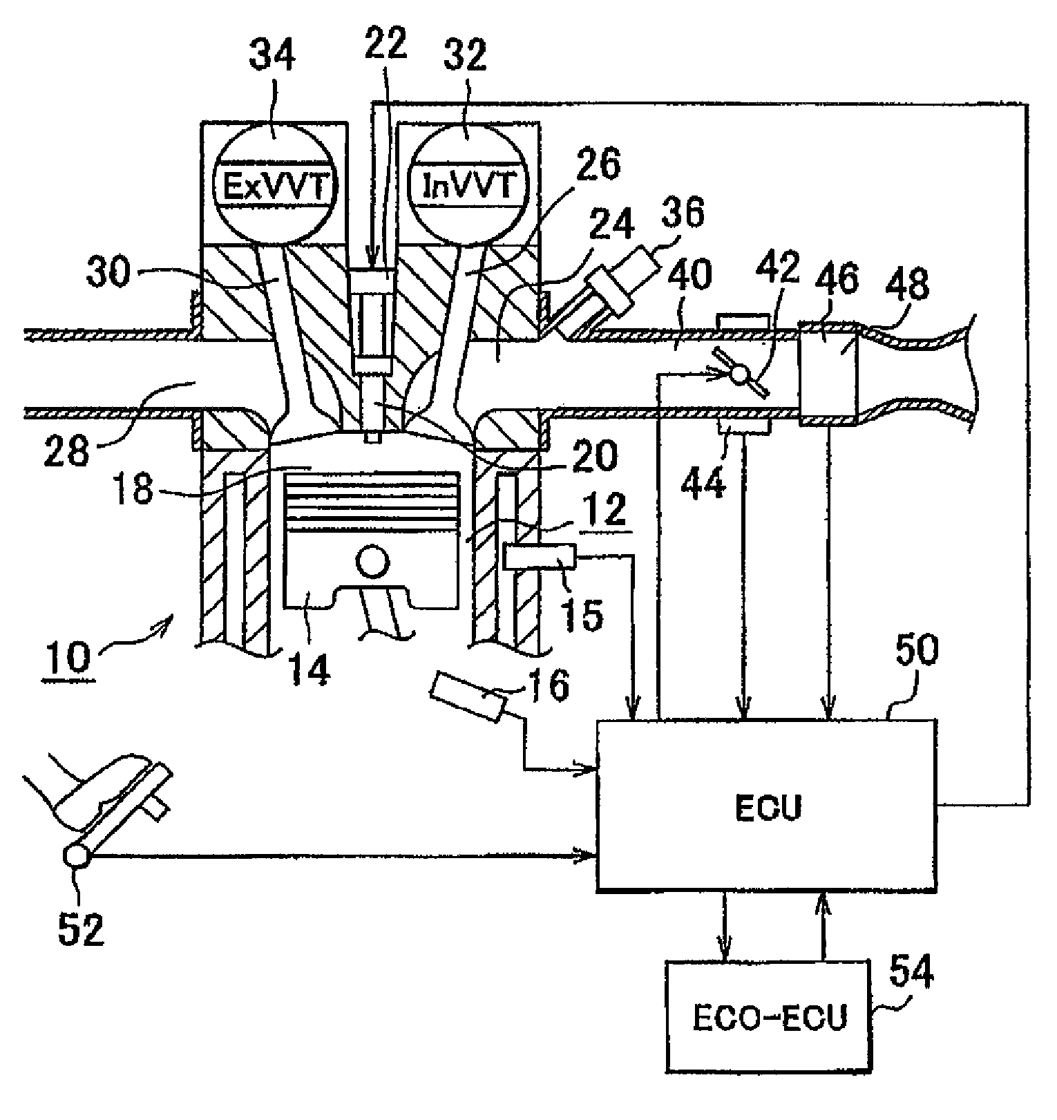
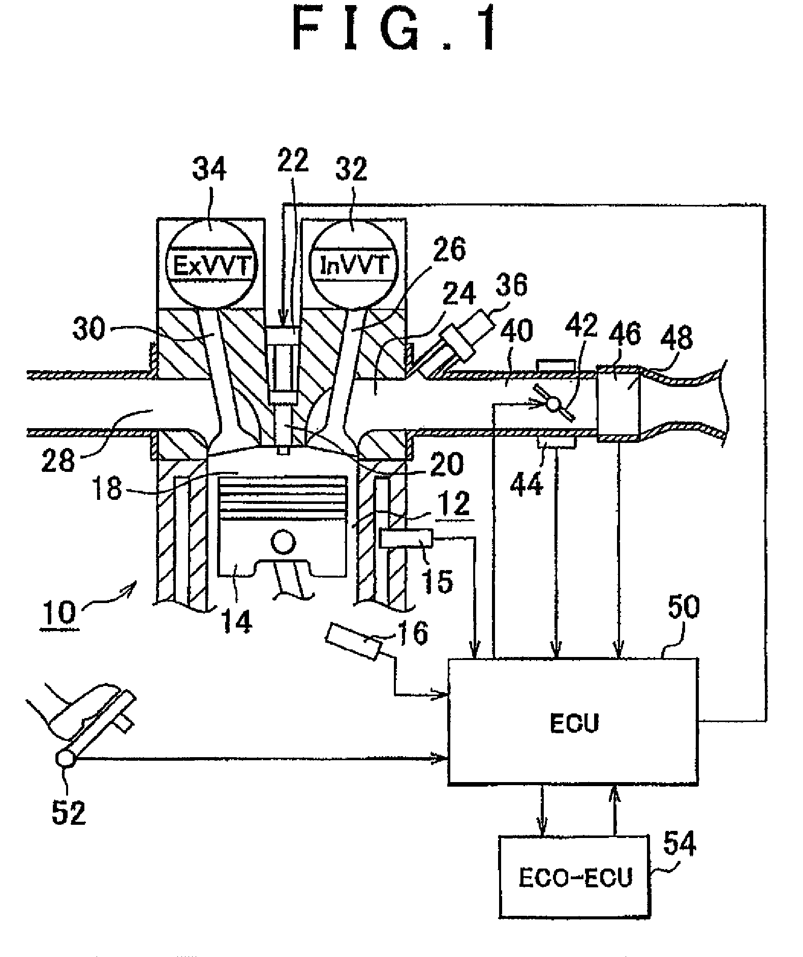
[0073]FIG. 1 is a view schematically showing the structure of an internal combustion engine system according to a first embodiment of the invention. The system shown in FIG. 1 includes an internal combustion engine 10. The internal combustion engine 10 includes cylinders 12. Although FIG. 1 shows the cross-section of only one cylinder 12, the internal combustion engine 10 actually includes the plurality of cylinders 12. A piston 14 is arranged in each of the cylinders 12. Each piston 14 is connected to a crankshaft (not shown) via a connecting rod. A coolant temperature sensor 15 (a coolant temperature detection unit) 15 that detects the temperature of a coolant is fitted to each cylinder 12. An engine speed sensor 16 that transmits a signal indicating the rotational speed of the internal combustion engine 10 is provided near the crankshaft.

[0074]A spark plug 20 is fitted at the center of the ceiling (...

second embodiment

of the Invention

[0122]A system according to a second embodiment of the invention has the same structure as that of the system according to the first embodiment of the invention. The system according to the second embodiment of the invention executes the same control as the control executed by the system according to the first embodiment of the invention except that it is determined, based on the coolant temperature and the stop position of the piston in the initial intake-stroke cylinder, whether the opening / closing timing of the exhaust valve 30 should be delayed by the reference delay amount X0 in the autoignition prevention control that is executed when the internal combustion engine 10 is at standstill.

[0123]FIG. 6 is a graph showing the relationship between the coolant temperature and the amount of delay correction made to the reference delay amount X0 for the exhaust valve 30. FIG. 7 is a graph illustrating the opening / closing characteristic of the exhaust valve 30, which is e...

third embodiment

of the Invention

[0141]A system according to a third embodiment of the invention has the same structure as that of the system according to the first embodiment of the invention. The system according to the third embodiment of the invention executes the same control as the control executed by the system according to the second embodiment of the invention except that a control over the opening / closing characteristic of the intake valve 26 is executed during the autoignition prevention control.

[0142]FIG. 11 is a graph illustrating the control over the opening / closing characteristic of the intake valve 26 in the system according to the third embodiment of the invention. In the third embodiment of the invention, the opening / closing characteristic of the intake valve 26 is controlled so that the opening amount of the intake valve 26 of the initial intake-stroke cylinder matches a predetermined reference opening amount Y0 (engine-stop reference opening amount) during the autoignition preven...


PUM


Abstract

A control apparatus includes a detection unit that detects a stop request to an engine, a throttle closing control unit that, when the stop request is detected, adjusts an opening amount of a throttle valve to an engine-stop throttle valve opening amount smaller than a current opening amount an engine stop detection unit that detects a stop of the engine, an engine-stop exhaust valve control unit that adjusts an opening / closing characteristic of an exhaust valve of a cylinder that will be placed initially in an intake stroke when the engine is restarted so that, when the opening amount of the throttle valve is adjusted to the engine-stop throttle valve opening amount and a stop of the engine is detected, the exhaust valve has an engine-stop exhaust valve opening / closing characteristic by which a closing timing of the exhaust valve is more delayed than a current closing timing of the exhaust valve.

Description

BACKGROUND OF THE INVENTION[0001]1. Field of the Invention[0002]The invention relates generally to a control apparatus and method for an internal combustion engine, and, more specifically, to a control apparatus and method for an internal combustion engine provided with a throttle valve, an intake valve and an exhaust valve, the control apparatus and method controlling the state in a cylinder when the internal combustion engine is at standstill.[0003]2. Description of the Related Art[0004]Japanese Patent Application Publication No. JP-2005-48718 (JP-A-2005-48718) describes a system that prevents autoignition from occurring when an internal combustion engine is being started. The system determines whether the temperature of a coolant in the internal combustion engine is equal to or higher than a predetermined temperature, when a request to start the internal combustion engine is issued. When it is determined that the temperature of the coolant is equal to or higher than the predeterm...

Claims


Application Information

Patent Timeline
Patent Type & Authority Patents(United States)
IPC IPC(8): F02N11/08F02N11/00F02D13/02F02D17/00F02D29/02F02D41/04F02D41/06F02D43/00F02D45/00F02N19/00F02P5/15
CPCF02D13/0219F02D13/0249F02D13/0261F02D41/0002F02D41/042F02D41/065F01L1/34F01L2800/01F01L2800/03F02D2013/0292F02D2200/0414F02N11/0814F02N19/004Y02T10/42Y02T10/18Y02T10/12Y02T10/40
Inventor DEMURA, TAKAYUKI
Owner TOYOTA JIDOSHA KK
Why Eureka
Try Eureka