

Manufacturing method of metal member
a manufacturing method and metal technology, applied in the field of metal member manufacturing, can solve the problems of not being able to accurately form a desired shape by forging, large equipment, and rarely generating work hardening, and achieve the effect of suppressing work hardening
- Summary
- Abstract
- Description
- Claims
- Application Information
AI Technical Summary
Benefits of technology
Problems solved by technology
Method used
Image

Examples
embodiment 1
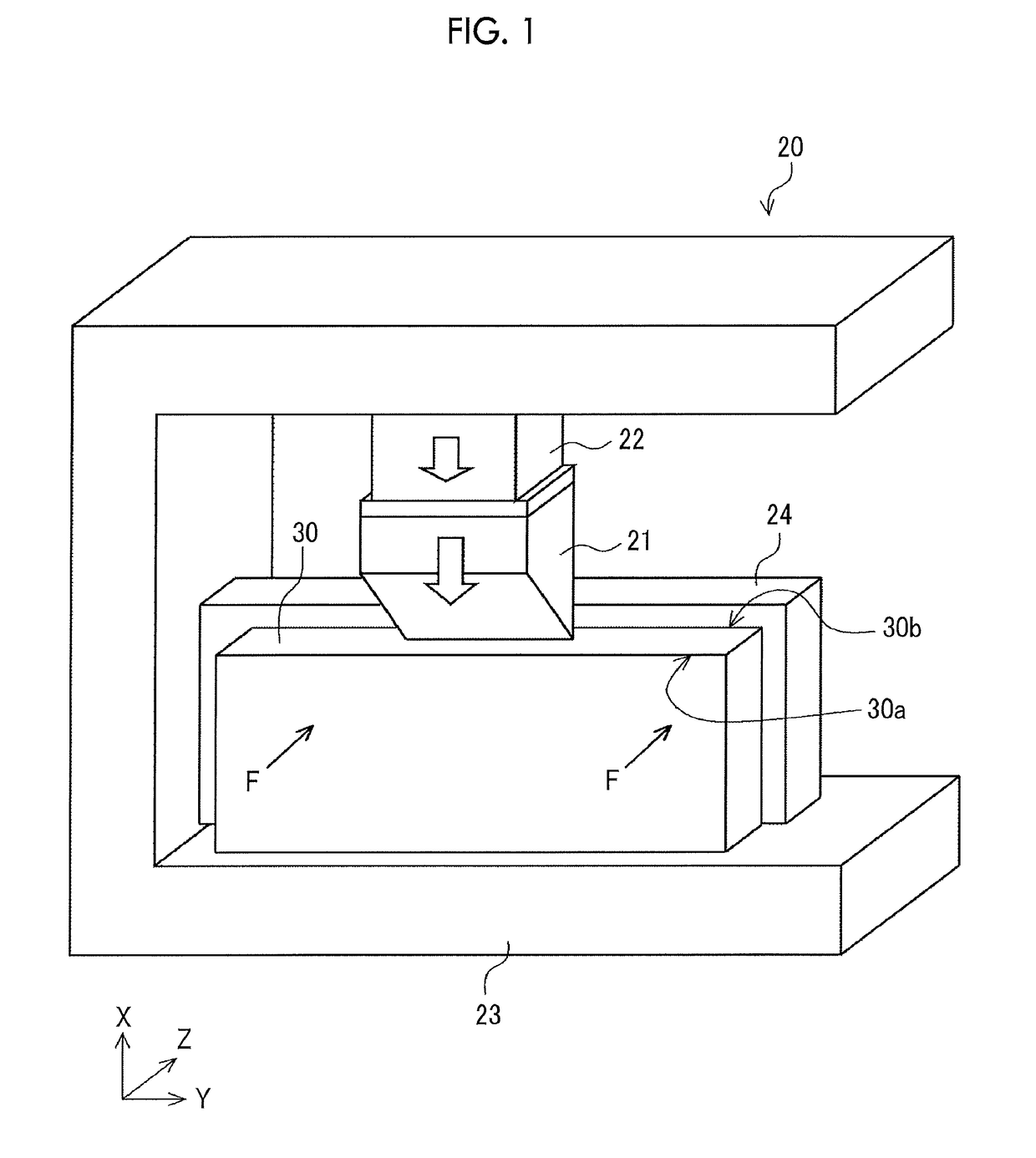
[0042]The configuration of a processing apparatus 20 used in a manufacturing method of a metal member according to Embodiment 1 will be described with reference to FIG. 1. Specifically, the processing apparatus 20 is a press apparatus. FIG. 1 is a perspective view schematically illustrating the configuration of the processing apparatus 20 used in the manufacturing method of the metal member according to Embodiment 1. The right-hand xyz coordinate system illustrated in FIG. 1 is an expedient for describing the positional relationships of constituent elements.
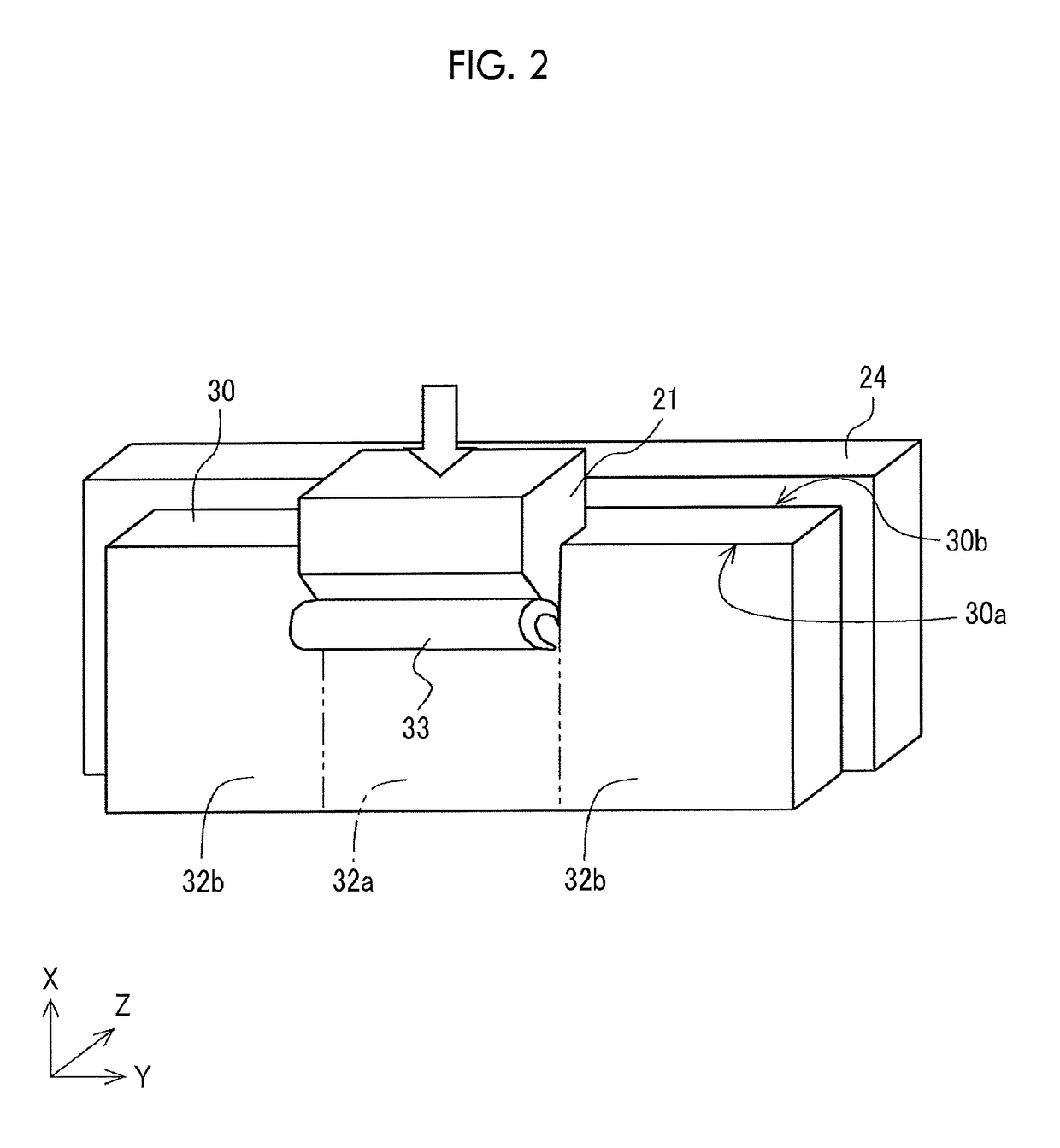
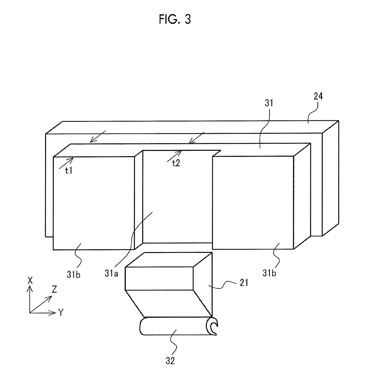
[0043]As illustrated in FIG. 1, the processing apparatus 20 includes a cutting edge 21, a slide 22, a main body 23, and a fixing stand 24. The slide 22 is attached to the main body 23 to be movable in an up-down direction (X-axis direction). The cutting edge 21 is a tool for shaving a metal plate 30, and is attached to a tip end of the slide 22. The metal plate 30 is a plate formed of a base metal such as aluminum, stainless, iro...
modification example 1
[0052]FIG. 5 is a perspective view illustrating a modification example of the metal member obtained by the manufacturing method of the metal member according to Embodiment 1. The right-hand xyz coordinate system illustrated in FIG. 5 is the same as the right-hand xyz coordinate system in FIG. 1. As illustrated in FIG. 5, a first surface 41a and a second surface 41b of a metal member 41 according to Modification Example 1 are perpendicular to the thickness direction of the metal member 41, first shaving and second shaving are performed on both the first surface 41a and the second surface 41b, and thus a thin portion 42a that is relatively thin and thick portions 42b that are relatively thick are formed in the metal member 41. With the manufacturing method of the metal member according to Embodiment 1, the thin portion that is relatively thin can be formed according to the design condition, and the reduction in weight of the metal member can efficiently be achieved.
modification example 2
[0053]FIG. 6 is a perspective view illustrating another modification example of the metal member obtained by the manufacturing method of the metal member according to Embodiment 1. The right-hand xyz coordinate system illustrated in FIG. 6 is the same as the right-hand xyz coordinate system in FIG. 1. As illustrated in FIG. 6, a first surface 51a and a second surface 51b of a metal member 51 according to Modification Example 2 are perpendicular to the thickness direction of the metal member 51, first shaving is performed on the first surface 51a out of the first surface Ma and the second surface 51b, and thus a thin portion 52a that is relatively thin and a thick portion 52b that is relatively thick are formed in the metal member 51. Two R portions 55a, 55b are formed on the boundary between the thin portion 52a and the thick portion 52b. A cutting edge 121a used for forming the metal member 51 has an R-portion forming portion 121aA corresponding to the two R portions 55a, 55b. With...
PUM
| Property | Measurement | Unit |
|---|---|---|
| thickness | aaaaa | aaaaa |
| length | aaaaa | aaaaa |
| thickness | aaaaa | aaaaa |
Abstract
Description
Claims
Application Information