
Multilayer parameter-varying fusion and deposition strategies for additive manufacturing

a technology of additive manufacturing and parameter fusion, applied in the direction of additive manufacturing apparatus, additive manufacturing process, applying layer means, etc., can solve the problems of affecting the delineation between fill strategy and contour scan, substantial anisotropy of physical properties, and limited number of side-by-side tracks

Active Publication Date: 2018-12-27
HEAVY METAL LLC
View PDF0 Cites 20 Cited by
  • Summary
  • Abstract
  • Description
  • Claims
  • Application Information

AI Technical Summary

Benefits of technology

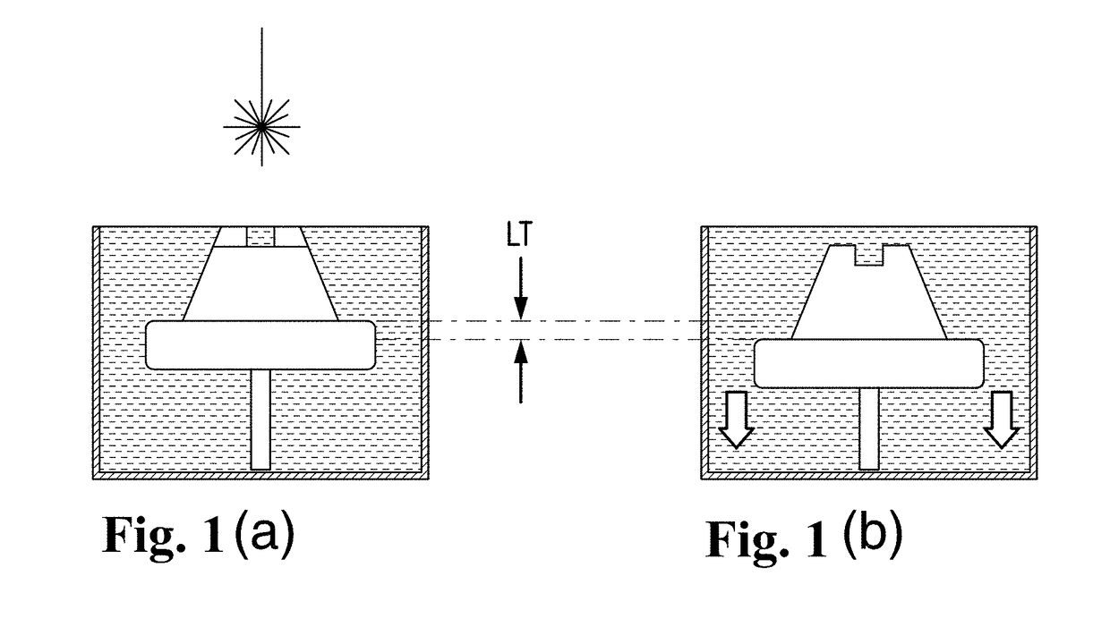
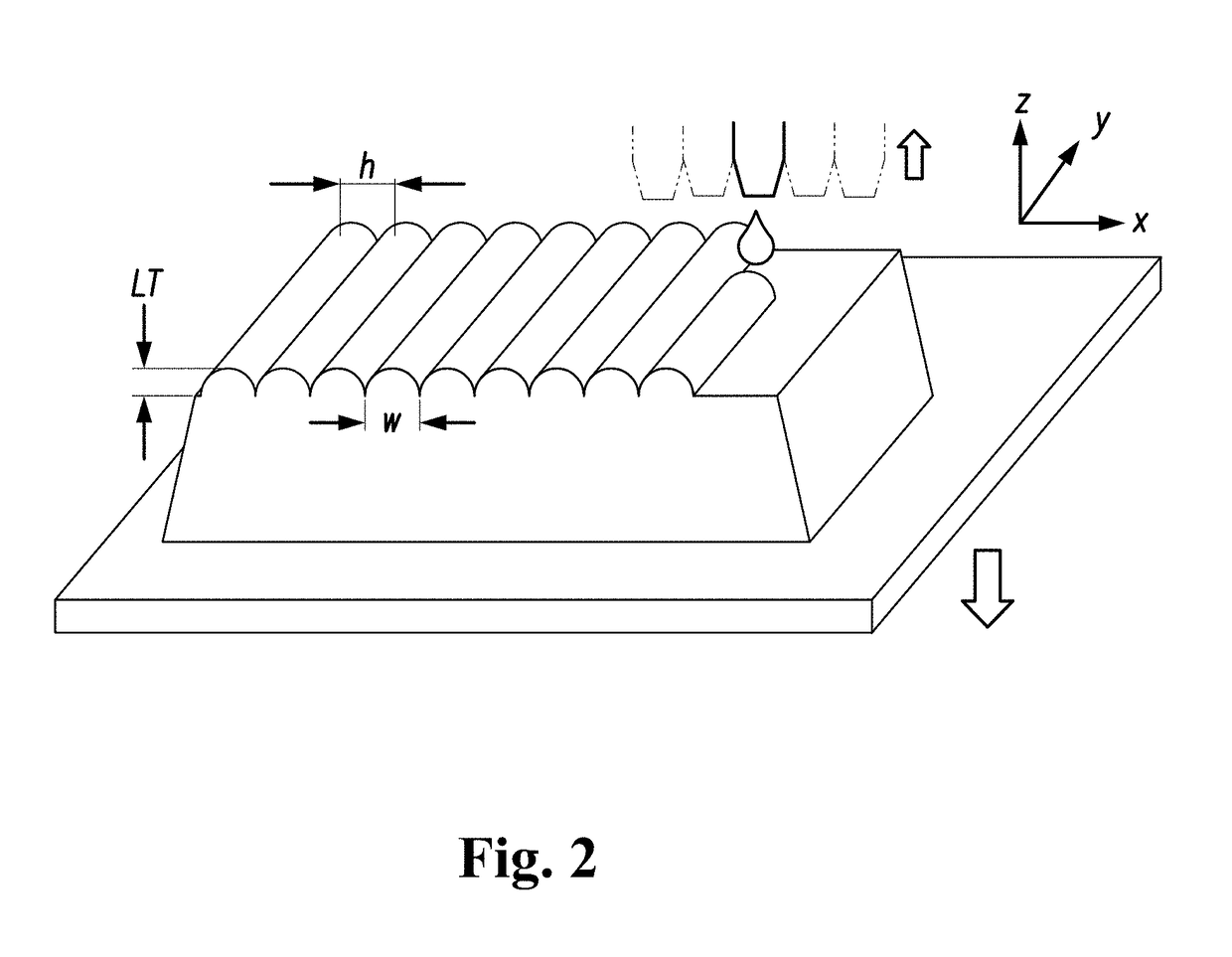
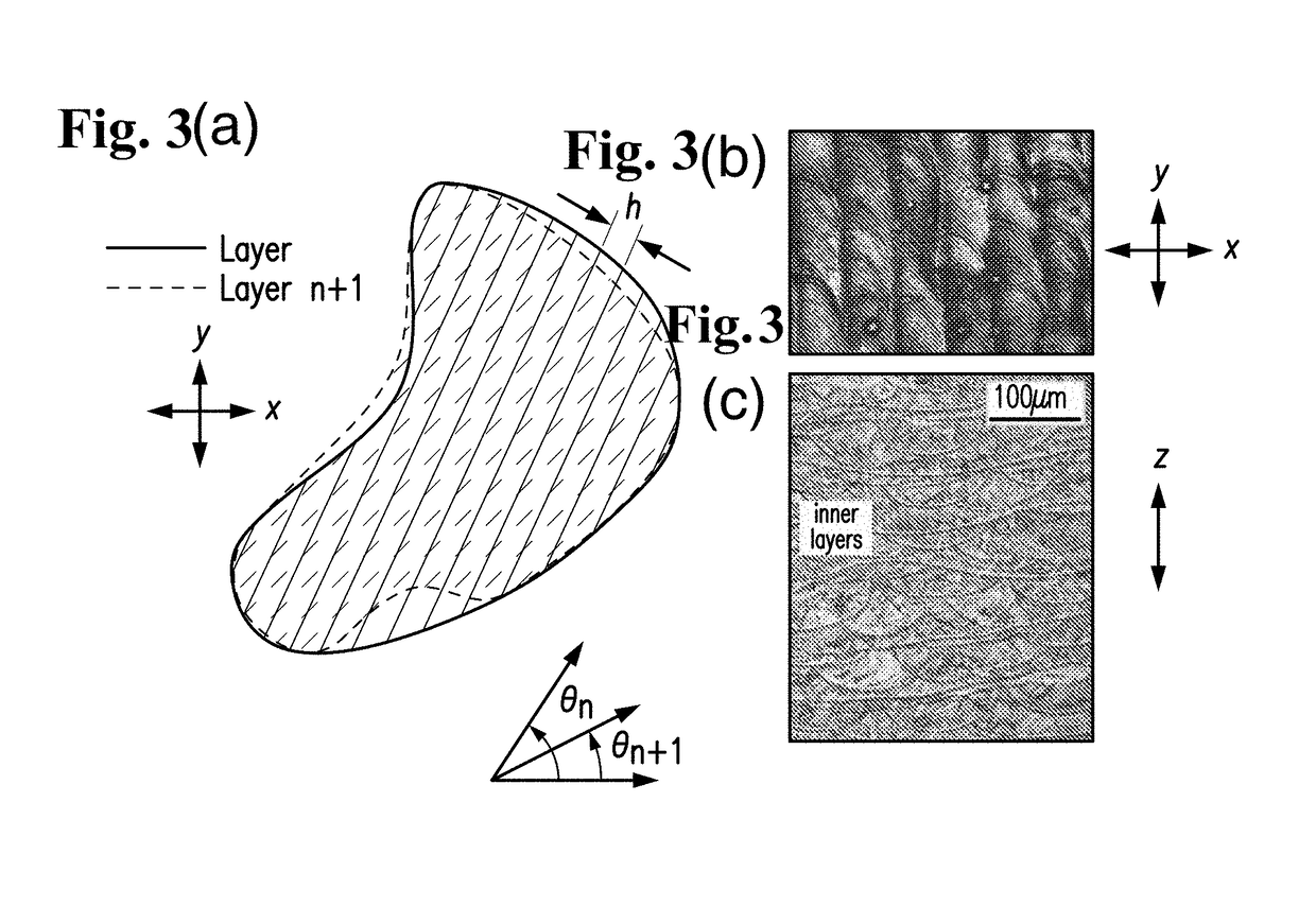
The present invention provides a solution for designing scanning strategies by using different sized and shaped tracks or track cross sections to define the position of scan paths across a region including parts of successive layers. This approach helps to improve the accuracy and efficiency of the scanning process.

Problems solved by technology

In the prior example of scanning all tracks in a single direction, no track boundaries are crossed by progressing in the scan direction (or anti-parallel to it), leading to substantial anisotropy in physical properties.
Multiple contour scan tracks can be placed side-by-side, but the number of such side-by-side tracks is often limited to one, two, or three.
Additionally, the delineation between fill strategies and contour scans is somewhat blurred when larger numbers of contour scans are employed near the surfaces of printed articles.

Method used


Image

  • Multilayer parameter-varying fusion and deposition strategies for additive manufacturing
  • Multilayer parameter-varying fusion and deposition strategies for additive manufacturing
  • Multilayer parameter-varying fusion and deposition strategies for additive manufacturing

Examples


example 1

[0143]In this example, material jetting via a fused deposition modeling printer with a single 400 um nozzle and a thermoplastic polymer feed wire consisting principally of polylactic acid is deployed to print three 20 mm cubes, each with different print parameters. Two cubes employ single track scan strategies with identical printer settings except that each cube is printed with a different extrusion volume ratio setting, and one cube employs a multi-track scan strategy with the same parameter settings as for the single track strategy except where alternation between two extrusion volume ratio settings is employed for printing successive tracks resulting in two distinct scan track geometries, along the lines of the strategy described for FIG. 26. In this case, only one cube of each type was printed; therefore, the standard deviations given for porosities are those measured across multiple images taken at different locations within the cube. The standard deviations given for mass are...

example 2

[0168]Material jetting via a fused deposition modeling printer with a single 400 um nozzle and a thermoplastic polymer feed wire consisting principally of polylactic acid is deployed to print three 20 mm cubes, each with different print parameters. Two cubes employ single track scan strategies with identical printer settings except that each cube is printed with a different extrusion volume ratio setting, and one cube employs a multi-track scan strategy with the same parameter settings as for the single track strategy except where alternation between two extrusion volume ratio settings is employed for printing successive tracks resulting in two distinct scan track geometries, along the lines of the strategy described for FIG. 16 and an exemplar image of which is depicted in Fig D. In this case, only one cube of each type was printed; therefore, the standard deviations given for porosities are those measured across multiple images taken at different locations within the cube. The sta...

example 3

[0193]In this example, porosity and mechanical property results are described for powder bed fusion printing of parts from two 316L stainless steel powders exhibiting for Example 3a a d50 of 18 um and for Example 3b a d50 of 45 um. Four 1 cm porosity cubes are printed for each of the three strategies (two single track, one multi-track) with some print settings described in Example 3a, and three 7.5 cm long (with 2.5 cm gauge) dogbone tensile coupons are printed for each of the two strategies (one single track, one multi-track) with some print settings described in Example 3b. The single track approaches in Example 3a deploy the scan strategies described for FIGS. 32c and 32b, and the multi-track strategy deploys the scan strategy described for FIG. 32a. The scan paths for the single and multi-track strategies in Example 3b are similar to those described for FIGS. 32c and 32a, respectively.


PUM

PropertyMeasurementUnit
Thicknessaaaaaaaaaa
Angleaaaaaaaaaa
Sizeaaaaaaaaaa

Abstract

The invention encompasses compositions and methods for designing or producing three-dimensional articles layer-by-layer, whereby the specific approach to build-up a region of a single layer by fusion, deposition of material, or other path-based process or non-path process that creates track-like geometries requires either differing track or track-like geometry, or track or track-like geometry printing parameters, within a region of a single layer or within adjoining regions of multiple layers, is disclosed. Employing this method, single layer or multilayer parameter-varying fusing and deposition strategies can be generated that reduce article fabrication time and improve article physical properties, in part by targeting a distribution of scan paths that satisfy covering problem overlap and / or dense packing criteria. Additionally, methods and compositions for designing or producing three-dimensional articles by altering the thickness of a material layer deposited during a print relative to the slice thickness or net displacement of a stage or of a material and / or energy-depositing print head, are disclosed. Employing this method can result in the reduction of article fabrication time and / or the improvement of printed article physical properties, where these results advantageous to printing are dependent on the print process, material properties, and feedstock properties employed during the print.

Description

FIELD OF THE INVENTION[0001]The invention encompasses compositions and methods for designing or producing three-dimensional articles layer-by-layer, whereby the specific approach to build-up a region of a single layer by fusion, deposition of material, or other path-based process or non-path process that creates track-like geometries requires either differing track or track-like geometry, or track or track-like geometry printing parameters, within a region of a single layer or within adjoining regions of multiple layers, is disclosed. Employing this method, single layer or multilayer parameter-varying fusing and deposition strategies can be generated that reduce article fabrication time and / or improve article physical properties, in part by targeting a distribution of scan paths that satisfy covering problem overlap and / or dense packing criteria. Additionally, methods and compositions for designing or producing three-dimensional articles by altering the thickness of a material layer...

Claims


Application Information

Patent Timeline
IPC IPC(8): B29C64/10B29C64/209C08L83/00
CPCB29C64/10B29C64/209C08L83/00B33Y10/00Y02P10/25
Inventor HOPKINS, ADAM BAYNETORQUATO, SALVATOREBEBERWYCK, BRANDON
Owner HEAVY METAL LLC
Learn More