
Shaped composite ply layups and methods for shaping composite ply layups

a technology of composite materials and layups, applied in the field of composite components, can solve the problems of reducing the integrity of composite components, increasing manufacturing complexity, time and/or cost of composite components, and gaps in composite ply sub-assemblies

Active Publication Date: 2018-12-27
GENERAL ELECTRIC CO
View PDF9 Cites 31 Cited by
  • Summary
  • Abstract
  • Description
  • Claims
  • Application Information

AI Technical Summary

Benefits of technology

This patent is about a new invention and its benefits. The technical effects of the invention will be explained in part through the description, or you can learn more through practicing the invention.

Problems solved by technology

The irregular finished edges as well as the relative motion between the plies may leave gaps in an assembly of composite ply sub-assemblies, such as an assembly of composite ply layups, composite plies, composite ply packs, etc.
Such gaps may require a filler material and / or additional densification material to reduced or eliminate the gaps, which may increase manufacturing complexity, time, and / or cost of composite components.
Further, such gaps may reduce the integrity of the composite component, which may decrease part yield and increase part scrap rate, as well as decrease time on wing and unplanned service calls for repairs.

Method used


Image

  • Shaped composite ply layups and methods for shaping composite ply layups
  • Shaped composite ply layups and methods for shaping composite ply layups
  • Shaped composite ply layups and methods for shaping composite ply layups

Examples


Embodiment Construction

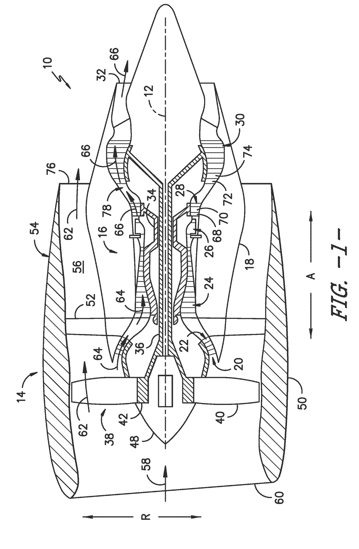
[0020]Reference will now be made in detail to present embodiments of the invention, one or more examples of which are illustrated in the accompanying drawings. The detailed description uses numerical and letter designations to refer to features in the drawings. Like or similar designations in the drawings and description have been used to refer to like or similar parts of the invention. As used herein, the terms “first,”“second,” and “third” may be used interchangeably to distinguish one component from another and are not intended to signify location or importance of the individual components. The terms “upstream” and “downstream” refer to the relative direction with respect to fluid flow in a fluid pathway. For example, “upstream” refers to the direction from which the fluid flows and “downstream” refers to the direction to which the fluid flows.

[0021]Referring now to the drawings, wherein identical numerals indicate the same elements throughout the figures, FIG. 1 is a schematic c...


PUM

PropertyMeasurementUnit
lengthaaaaaaaaaa
lengthaaaaaaaaaa
temperaturesaaaaaaaaaa

Abstract

Ply layups and methods for forming composite components are provided. For example, a method for forming a composite component comprises laying up a plurality of composite plies to form a composite ply layup; partially processing the composite ply layup to form a green state layup; machining the green state layup; assembling the green state layup with one or more sub-assemblies; and processing the green state layup and the one or more sub-assemblies to form the composite component. In an exemplary embodiment, the composite component is a turbine nozzle airfoil. Another exemplary method comprises laying up a plurality of composite plies to form a composite ply layup; compacting the composite ply layup to form a green state layup; machining the green state layup; assembling the green state layup with one or more sub-assemblies; and processing the green state layup and the one or more sub-assemblies to form the composite component.

Description

FIELD[0001]The present subject matter relates generally to composite components. More particularly, the present subject matter relates to composite material ply layups and methods for shaping composite material ply layups.BACKGROUND[0002]More commonly, non-traditional high temperature composite materials, such as ceramic matrix composite (CMC) and polymer matrix composite (PMC) materials, are being used in applications such as gas turbine engines. Components fabricated from such materials have a higher temperature capability compared with typical components, e.g., metal components, which may allow improved component performance and / or increased engine temperatures. Composite components may provide other advantages as well, such as an improved strength to weight ratio.[0003]Often, composite components are formed at least in part from a plurality of plies of the composite material. The composite plies may be cut from a tape or sheet of a composite matrix, which also may comprise other...

Claims


Application Information

Patent Timeline
Patent Type & Authority Applications(United States)
IPC IPC(8): B29C70/30B29C70/54B29D99/00F01D5/18F01D5/28B32B5/02B32B18/00
CPCB29C70/30B29C70/545B29D99/0028F01D5/18F01D5/282F01D5/284F05D2230/23B32B18/00B32B1/00B29L2031/08B32B2307/306B32B2603/00F05D2300/6033B32B5/02B32B5/16B32B27/08B32B27/281B32B27/285B32B27/288B32B27/34B32B27/36B32B27/365B32B27/38F01D9/041F05D2240/121B32B2260/046B32B2260/021B32B2260/025B32B2262/105B32B2262/106B32B2262/10B32B2264/107B29C70/302B29L2031/7504B29C70/342C04B2235/428C04B2235/5224C04B2235/5244C04B2235/5248C04B2235/616C04B2237/365C04B2237/38C04B2237/385C04B2237/52C04B2235/5228C04B2235/5276C04B2237/341C04B2237/343
Inventor GALLIER, KIRK D.SIZEMORE, NATHAN CARL
Owner GENERAL ELECTRIC CO
Learn More