Methods for Manufacturing Tempered Vacuum Glass and Production Lines Therefor

Active Publication Date: 2018-12-27
LUOYANG LANDGLASS TECH CO LTD
View PDF12 Cites 2 Cited by
  • Summary
  • Abstract
  • Description
  • Claims
  • Application Information

AI Technical Summary

Problems solved by technology

Soon afterwards, some research had been made around this technology at home and abroad, but due to the process reasons, the manufactured vacuum glass was non-tempered vacuum

Method used


Image

  • Methods for Manufacturing Tempered Vacuum Glass and Production Lines Therefor
  • Methods for Manufacturing Tempered Vacuum Glass and Production Lines Therefor
  • Methods for Manufacturing Tempered Vacuum Glass and Production Lines Therefor

Examples


embodiment 1

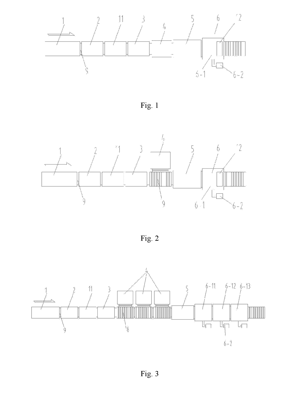
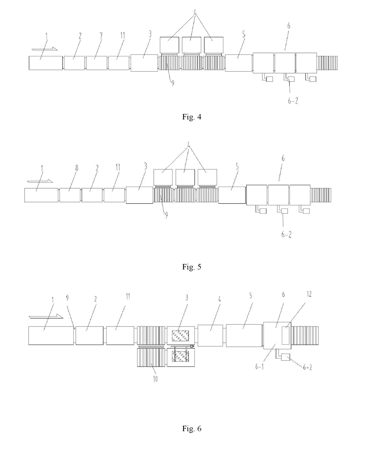
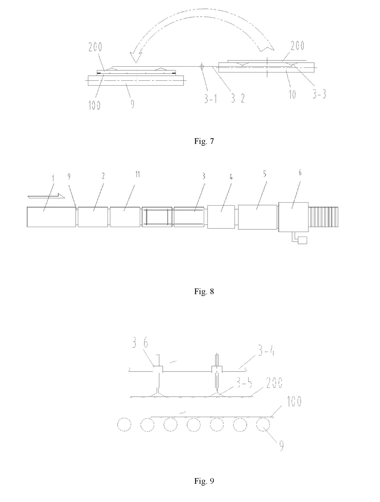
[0056]FIG. 1 and FIG. 10 show the first specific embodiment of a tempered vacuum glass production line in the present disclosure. In this embodiment, the production line specifically includes a first conveying device 9, e.g., a conveying roller bed, and a metalized layer manufacturing device 1, a solder placing device 2, a first preheating device 11, a superposing device 3, a soldering and edge-sealing device 4, a second preheating device 5, a vacuumizing system 6 and a sealing device 12 which are connected in sequence by a first conveying device 9, wherein the first preheating device 11 is used for heating glass substrates to 60-150° C. before the glass substrates are superposed, and then the soldering and edge-sealing device 4 performs edge sealing treatment; of course, the first preheating device 11 can also be arranged on the next station of the superposing device 3, to heat the overall superposed glass substrates to 60-150° C. The sealing device 12 is arranged in the vacuumizin...

embodiment 2

[0075]FIG. 2 shows a second specific embodiment of a tempered glass production line. This embodiment is substantially the same as embodiment 1 in structure, and the difference lies in that the soldering and edge-sealing device 4 is arranged on one side of the first conveying device 9, a push mechanism arranged on the first conveying device 9 pushes the glass substrate into the soldering and edge-sealing device 4, at the moment, the conveying direction of the soldering and edge-sealing device 4 is perpendicular to that of the first conveying device 9.

embodiment 3

[0076]FIG. 3 shows a third specific embodiment of a tempered glass production line. This embodiment is substantially the same as embodiment 2 in structure, and the difference lies in that the number of the soldering and edge-sealing device 4 is three, and of course, the number of the soldering and edge-sealing device 4 can be increased or reduced according to the working efficiency of each station on the production line; in this way, a plurality of soldering and edge-sealing devices 4 can be arranged on the most time-consuming soldering and edge-sealing process of the whole production line, so that the production efficiency is improved; moreover, the conveying direction of the soldering and edge-sealing devices 4 is perpendicular to that of the first conveying device 9, so that the glass substrate can selectively enter any vacant soldering and edge-sealing device 4. The vacuum chambers 6-1 (see FIG. 2 or FIG. 1) include a front auxiliary vacuum chamber 6-11, a main vacuum chamber 6-...


PUM

PropertyMeasurementUnit
Temperatureaaaaaaaaaa

Abstract

The disclosure discloses a manufacturing method of tempered vacuum glass. At least one glass substrate constituting the tempered vacuum glass is reserved with an extraction opening, and the manufacturing method comprises the following steps: (1) manufacturing metalized layers, and performing tempering or thermal enhancement on the glass substrates; (2) placing a metal solder on the metalized layers; (3) superposing the glass substrates; (4) heating the overall glass substrates to 60-150° C.; (5) hermetically sealing the glass substrates under the condition of ensuring the heating temperature; (6) heating; (7) vacuumizing; and (8) closing the extraction opening, thus accomplishing the manufacturing process. The manufacturing method in the present disclosure can greatly reduce the stress when the two glass substrates are sealed, improve the soldering strength and prolong the service life of the tempered vacuum glass. The disclosure further discloses a tempered vacuum glass production line based on the above manufacturing method.

Description

TECHNICAL FIELD[0001]The present disclosure relates to the manufacturing field of vacuum glass, and particularly relates to a manufacturing method of one type of tempered vacuum glass and a tempered vacuum glass production line based on the manufacturing method.BACKGROUND ART[0002]Vacuum glass with excellent heat insulation, sound insulation and energy-saving effects represents the development direction of future new-generation energy-saving architectural glass, and is increasingly widely popularized and used. Vacuum glass was first researched in the 1990s, for example, Australian Patent No. AU94192667.2 disclosed a manufacturing method of vacuum glass, which opened the door to vacuum glass research. Soon afterwards, some research had been made around this technology at home and abroad, but due to the process reasons, the manufactured vacuum glass was non-tempered vacuum glass, which did not meet the standards of architectural safety glass and greatly obstructed the application of v...

Claims


Application Information

Patent Timeline
IPC IPC(8): E06B3/677E06B3/673B23K1/00B23K1/002B23K1/005B23K37/04B23K1/20
CPCE06B3/6775E06B3/6736E06B3/67373B23K1/0008B23K1/002B23K1/0056B23K37/04B23K1/20B23K2103/54C03C27/08C03B23/24C03B23/245Y02P40/57
Inventor ZHAO, YAN
Owner LUOYANG LANDGLASS TECH CO LTD
Why Eureka
Try Eureka