Assembly for a spreader connection between a turbine casing and a turbine engine ring element

a spreader connection and turbine engine technology, applied in the direction of machines/engines, climate sustainability, sustainable transportation, etc., can solve the problems of limiting the possibility of increasing the temperature of the turbine, affecting the operation of the turbine, etc., to achieve the effect of flexible and permanent assembly adaptation

Active Publication Date: 2018-12-27
SN DETUDE & DE CONSTR DE MOTEURS DAVIATION S N E C M A
View PDF2 Cites 14 Cited by
  • Summary
  • Abstract
  • Description
  • Claims
  • Application Information

AI Technical Summary

Benefits of technology

[0041]to be connected to the annular tongue by means of the eccentric, the operating rod of which, which extends parallel to the axis along which the annular tongue and the sectorized annular element extend coaxially, is engaged without clearance in a first passage in the annular tongue and can be operated for adjusting the radial distance, two groups of two pins of the spreader, each parallel to the axis, being mounted, with a least a radial clearance, in some of the passages, that are spaced apart from on another circumferentially, in the sectorized annular element, it is possible, in addition, to distribute the bearing surfaces appropriately and accurately at preferred places, thereby further facilitating keeping the stresses under control.
[0042]Notable among the advantages of the proposed assembly is the importance of the vice system device used. The pin is mounted with clearance in the bore. This clearance remains when the engine is hot, thereby helping to overcome the obstacles of the manufacturing tolerances and of the differential expansions that can damage the second material; the pin is pressed against the upper surfa

Problems solved by technology

In addition, the use of metal limits the possibilities of increasing the temperature where the turbine is located, which could have been used to improve the performance of the turbine engine.
Comparable differential expansion problems exist both where the outer platform sectors of blades of the HP turbine distributor are situated, and also where the first stage of the LP turbine distributors (LPD1) is situated.
Unfortu

Method used


Image

  • Assembly for a spreader connection between a turbine casing and a turbine engine ring element
  • Assembly for a spreader connection between a turbine casing and a turbine engine ring element
  • Assembly for a spreader connection between a turbine casing and a turbine engine ring element

Examples


Embodiment Construction

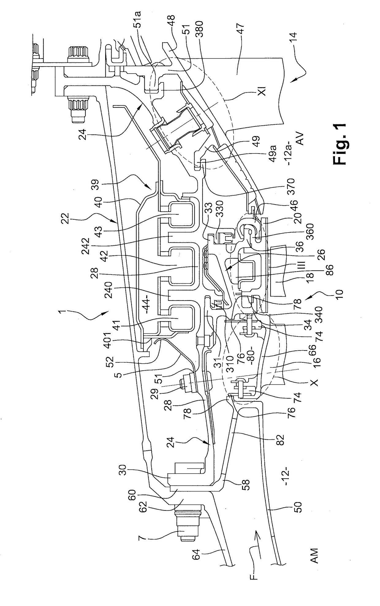
[0072]FIG. 1 shows part of a known turbine engine 1, such as an aircraft turbojet, turbofan, or turboprop comprising a high-pressure turbine (HP) 10 placed axially (along axis X) downstream (AV) from a combustion chamber 12, and upstream (AM) from a low-pressure turbine (LP) 14 of the turbine engine.

[0073]The combustion chamber 12 comprises a circularly symmetrical outer wall 50 connected at its downstream end to a radially inner end of a frustoconical wall 58 which, at its radially outer end, has a radially outer annular flange 60 for fastening to a corresponding annular flange 62 of an outer casing 64 of the chamber. The high-pressure turbine 10 in the example comprises a single turbine stage with a distributor 16 formed by an annular row of fixed straightening blades, and a bladed wheel 18 mounted to rotate downstream from the distributor 16. The low-pressure turbine 14 comprises a plurality of turbine stages with each stage comprising a distributor and a bladed wheel. Only the d...


PUM


Abstract

An assembly comprising ring sectors made of a first material, the sectors being placed circumferentially end to end and suspended from an outer casing, and radial positioning means comprising at least one annular tongue made of a different material, for fastening the ring sectors to the outer casing, by an annular support. The radial positioning means further comprise an eccentric spreader engaged on one side with said at least one annular tongue and, on the other side, with the sectorized annular element, and acting to enable the distance between the annular tongue and the sectorized annular element to be adjusted radially.

Description

[0001]This application claims the benefit of French Patent Application No. 1755847, filed Jun. 26, 2017, the contents of which is incorporated by reference herein.BACKGROUND OF THE INVENTION[0002]On a gas turbine engine for an aircraft, this invention relates to the connection between an annular tongue, made of a first material and fastened to an annular outer casing of a turbine, and a sectorized annular element, made of a second material having a coefficient of thermal expansion different from that of the first material.[0003]The sectorized annular element may in this description typically comprise one of the following:[0004]ring sectors, which are placed circumferentially end to end and suspended from the outer casing, or[0005]outer platform sectors of blades of a distributor of said turbine,both thus being made of said second material.[0006]As a sectorized annular element, the turbine rings make it possible to define a portion of the outer stream of the turbine, in particular of...

Claims


Application Information

Patent Timeline
IPC IPC(8): F01D25/24
CPCF01D25/246F05D2220/323F05D2240/14F05D2300/50212F05D2300/6033F05D2240/11F05D2240/80F01D11/24F05D2230/644Y02T50/60F01D11/22
Inventor LEPRETRE, GILLES GERARD CLAUDETESSON, THIERRY GUY XAVIERIIIAND, HUBERT JEAN-YVESQUENNEHEN, LUCIEN HENRI JACQUESGIMAT, MATTHIEU ARNAUD
Owner SN DETUDE & DE CONSTR DE MOTEURS DAVIATION S N E C M A
Why Eureka
Try Eureka