Adjustment and/or drive unit, wind power plant having such an adjustment and/or drive unit, and method for controlling such an adjustment and/or drive unit

a technology of adjustment and/or drive unit, which is applied in the direction of wind energy generation, mechanical equipment, machines/engines, etc., can solve the problems of increased wear and maintenance requirements of service brakes, increased rigidity, and undesirable dynamic effects of nacelles and/or rotary platforms, so as to reduce undesirable dynamic effects, reduce bearing size, and increase rigidity

Active Publication Date: 2018-12-27
LIEBHERR COMPONENTS BIBERACH GMBH
View PDF12 Cites 14 Cited by
  • Summary
  • Abstract
  • Description
  • Claims
  • Application Information

AI Technical Summary

Benefits of technology

[0017]Accordingly, the invention suggests adapting, to the external loads, the bracing of the adjusting drives against each other during the movement of the assemblies being adjusted, so as to not unnecessarily burden the adjusting drives, and to also achieve sufficient bracing and thus damping of the dynamic effects under unfavorable conditions. According to the invention, the control device comprises a bracing-adjustment device for variably adjusting the intensity of the bracing of the adjusting drives as a function of a variable external load on the assemblies being adjusted, wherein said intensity can be determined by means of a load determining device. If strong bracing is necessary due to the external loads, the bracing-adjustment device provides greater and / or sufficiently strong bracing. Weaker bracing can be provided if conditions permit, so as not to burden the adjusting drives unnecessarily. This manner of intelligent adaptation of the bracing of the adjusting drives to the external loads on the components being adjusted, in particular the nacelle which is rotated and the rotor attached to the same, or on the revolving platform of a crane, allows the use of smaller and / or fewer adjusting drives, as well as the prevention of premature wear, all the while still minimizing unwanted dynamic effects even under unfavorable conditions. Maintenance requirements are reduced in this case.
[0068]On the other hand, the drives mounted in the preassembled installation assembly are more easily accessible, which facilitates maintenance, repair and replacement. In particular, however, it is possible to avoid the flexibility and compliance of the to-date conventional adjusting drive mounts and the azimuth bearing mounts, said flexibility and compliance arising in the currently-prevalent machine supports of conventional wind power plants.

Problems solved by technology

Due to play in the toothing, this rotation results in mobility in the drive trains, such that, despite the use of multiple adjusting drives, the nacelle and / or the rotary platform can react with undesirable dynamics, for example in the form of rotatory vibrations.
The aforementioned mobilities and elasticities in the drive train can be due to a variety of causes in this case—for example, in addition to backlash in the tooth engagement between the pinion and the crown gear, there can be compliances in the gear units which are employed, or compliances in the mounts of the adjusting drives, which are usually attached to appropriate machine supports which possess only limited stiffness.
The disadvantage of this, however, is that increased wear can occur on the drives, the adjusting drives must be oversized in order to not only be able to apply the adjusting forces per se, but also to overcome the braking force.
At the same time, the service brake is subject to a high degree of wear and maintenance requirements.
However, under unfavorable conditions, such as high alternating loads, swaying and / or insufficient suppression of the dynamic effects can occur nonetheless.
On the other hand, the adjusting drives and the drive train are unnecessarily loaded in calm phases—for example, with no wind—in which no major damping of dynamic effects would be necessary, thereby leading to premature wear.
On the other hand, overloading can occur in such adjusting drive systems, which can lead to damage to individual adjusting drives or destruction of components.
Since, in a system with a plurality of adjusting drives which are used in a force-locking configuration, the individual adjusting drives cannot be designed in such a manner that they each individually transmit the entire force, asymmetrical loads can lead to overload of a drive.
If each drive were individually designed in such a manner that it alone could transmit the entire maximum load, the system as a whole would be drastically oversized.
When the potential overloads mentioned above occur, it is possible in some cases that difficult to replace components will be destroyed.
The greatest damage is caused by the area in which all drives direct their forces being destroyed, because in this case, emergency operation by means of only a few adjusting drives is no longer possible.
In a crown gear drive of the aforementioned type, as used in azimuth modules of wind power plants or large slewing rings—for example, of cranes—destruction of the crown gear and / or the tooth flanks of such a crown gear brings the entire system down, resulting in a very long downtime since the crown gear cannot be directly reconstructed.
Such mechanical breaking points on the output shaft of the adjusting drives do indeed protect the crown gear and the gear unit of the adjusting drives from destruction and / or damage, and only a relatively simpler, cheaper component must be replaced.
Nevertheless, there are downtimes for the repair, and a corresponding loss of output.

Method used


Image

  • Adjustment and/or drive unit, wind power plant having such an adjustment and/or drive unit, and method for controlling such an adjustment and/or drive unit
  • Adjustment and/or drive unit, wind power plant having such an adjustment and/or drive unit, and method for controlling such an adjustment and/or drive unit
  • Adjustment and/or drive unit, wind power plant having such an adjustment and/or drive unit, and method for controlling such an adjustment and/or drive unit

Examples


Embodiment Construction

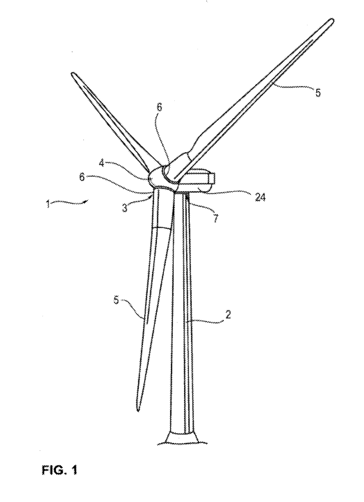
[0088]As shown in FIG. 1, the rotor 3 of a wind power plant 1 can be rotatably mounted about a horizontal rotor axis on a nacelle 24 and / or a turbine house, which can be arranged on a tower 2 and rotated about an upright axis, to enable orienting the rotor 3 with respect to the wind direction. The generator, control assemblies for the same, and additional energy converter assemblies and auxiliary assemblies can be housed in a conventional manner in said nacelle 24.

[0089]The rotor hub 4 rotatably mounted on the nacelle 24 about the horizontal rotor axis carries a plurality of rotor blades 5 which are rotatably mounted on the rotor hub 4 about rotor blade longitudinal axes, in such a manner that the blade angle or pitch angle of the rotor blades can be adapted to operating conditions, in particular to the wind speed and the generation status of the wind power plant. For this purpose, pitch adjustment units and / or drive units can be included in a manner which is known per se.

[0090]To b...


PUM


Abstract

The present invention relates to adjustment and / or drive units which can be used in wind power plants for adjusting the azimuth angle of the nacelle of the wind power plant or the pitch angle of the rotor blades, wherein such an adjustment and / or drive unit has at least two adjusting drives for rotating two assemblies which are mounted so as to be rotatable relative to each other, and has a control device for controlling the adjusting drives. Said control device controls the adjusting drives in such a manner that the adjusting drives are braced relative to each other during the rotation of the two assemblies and / or when the assemblies are at standstill. The invention further relates to a wind power plant comprising such an adjustment and / or drive unit, and to a method for controlling such an adjustment and / or drive unit. According to the invention, the control device comprises a bracing-adjustment device for variably adjusting the intensity of the bracing of the adjusting drives as a function of a variable external load on the assemblies being adjusted, wherein said intensity can be determined by means of a load determining device. According to another aspect of the invention, an overload protection is included, wherein the individual loads of the individual adjusting drives are determined by load determining devices and, in the event that an adjusting drive reaches overload, the distribution of the drive torques is modified in such a manner that the adjusting drive reaching overload is relieved or at least not further loaded, and at least one further adjusting drive is more heavily loaded in a supporting manner or is less heavily loaded in a bracing manner.

Description

CROSS-REFERENCE TO RELATED APPLICATIONS[0001]The present application is a continuation of International Application No. PCT / EP2016 / 001926, filed Nov. 18, 2016, which claims priority to German Patent Application Nos. 10 2015 015 070.7, filed Nov. 20, 2015; and 10 2016 002 006.7, filed Feb. 19, 2016, both of which are incorporated by reference herein in their entireties.BACKGROUND1) Technical Field[0002]The present invention relates to adjustment and / or drive units as can be used in wind power plants for adjusting the azimuth angle of the wind power plant nacelle or the pitch angle of the rotor blades, or in other large rotary mechanisms such as the slewing ring of a crane or an excavator, wherein such an adjustment and / or drive unit has at least two adjusting drives for rotating two assemblies which are mounted so as to be rotatable relative to each other, and has a control device for controlling the adjusting drives. Said control device controls the adjusting drives in such a manner...

Claims


Application Information

Patent Timeline
Patent Type & Authority Applications(United States)
IPC IPC(8): F03D7/02F03D7/04F03D17/00
CPCF03D7/0204F03D7/047F03D17/00F03D80/00F05B2240/40F05B2260/79F05B2270/1095F05B2270/329F05B2270/331F05B2270/335Y02E10/72F03D80/70F03D7/0248F05B2240/50F05B2270/321F05B2270/328F05B2270/32F03D7/0224
Inventor MULLER, JOHANNESDAHL, MARTINWENNHELLER, OLIVERCHRIST, CLEMENSFENKER, OLIVER
Owner LIEBHERR COMPONENTS BIBERACH GMBH
Why Eureka
Try Eureka