System and method for field calibration of a vision system imaging two opposite sides of a calibration object

a vision system and calibration object technology, applied in the field of machine vision systems, can solve the problems of high difficulty in calibrating all sensors, and the accuracy to which the target is measured in the field, and achieve the effect of simple field calibration

Inactive Publication Date: 2018-12-27
COGNEX CORP
View PDF14 Cites 51 Cited by
  • Summary
  • Abstract
  • Description
  • Claims
  • Application Information

AI Technical Summary

Benefits of technology

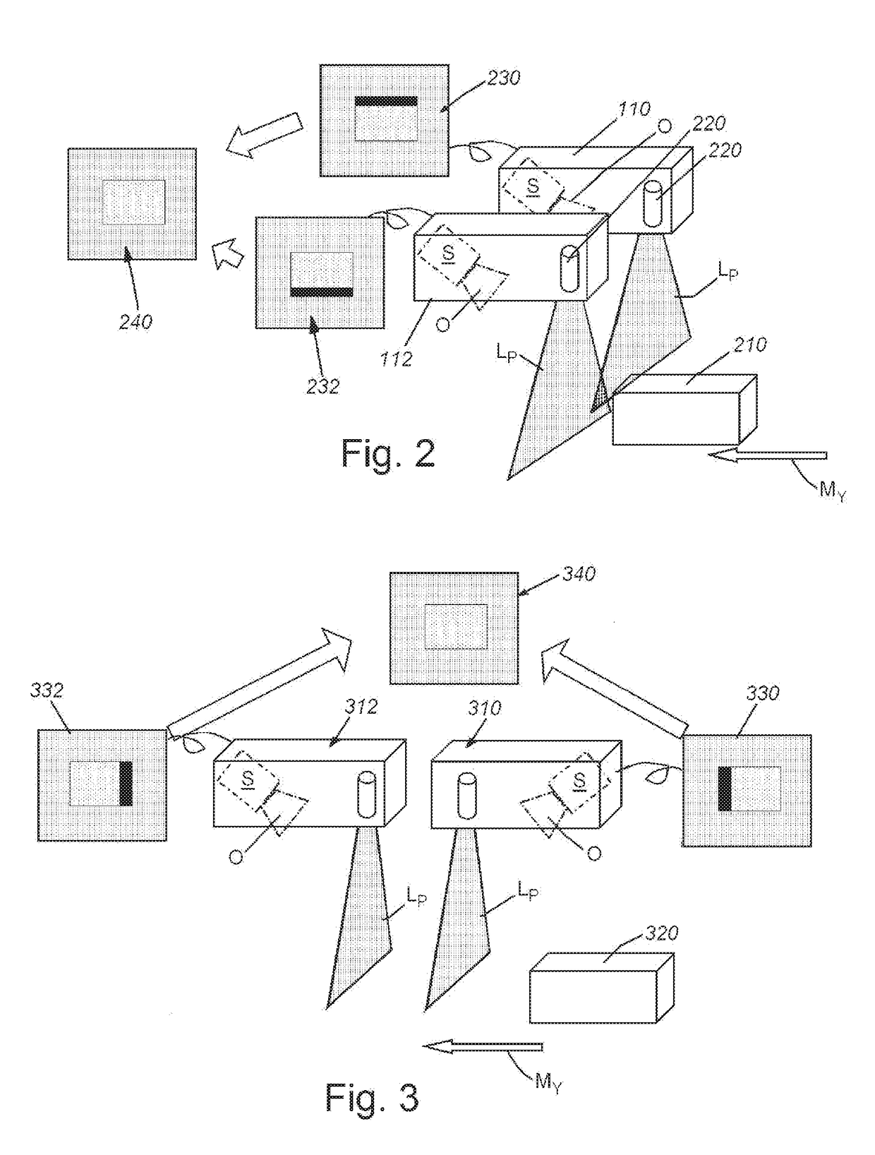
[0008]This invention overcomes disadvantages of the prior art by providing an easy-to-manufacture, easy-to-analyze calibration object which combines measurable and repeatable, but not necessarily accurate, 3D features—such as a two-sided calibration object / target in (e.g.) the form of a frustum, with a pair of accurate and measurable features, more particularly parallel faces separated by a precise specified thickness, so as to provide for simple field calibration of opposite-facing DS sensors. Illustratively, a composite calibration object can be constructed, which includes the two-sided frustum that has been sandblasted and anodized (to provide measurable, repeatable features), with a flange whose above / below parallel surfaces have been ground to a precise specified thickness. The 3D corner positions of the two-sided frustum are used to calibrate the two sensors in X and Y, but cannot establish absolute Z without accurate information about the thickness of the two-sided frustum; the flange provides the absolute Z information.

Problems solved by technology

It is often highly challenging to calibrate all sensors to a common coordinate space, particularly where the sensors are arranged to image opposing sides of an object under inspection (i.e. above and below the object), so as to accurately measure opposite sides of an object, such as for thickness measurements.
However, a disadvantage to relying on an accurate target is that the field calibration (and all subsequent measurements) are limited by the accuracy to which the target is measured.

Method used


Image

  • System and method for field calibration of a vision system imaging two opposite sides of a calibration object
  • System and method for field calibration of a vision system imaging two opposite sides of a calibration object
  • System and method for field calibration of a vision system imaging two opposite sides of a calibration object

Examples


Embodiment Construction

[0051]I. System Overview

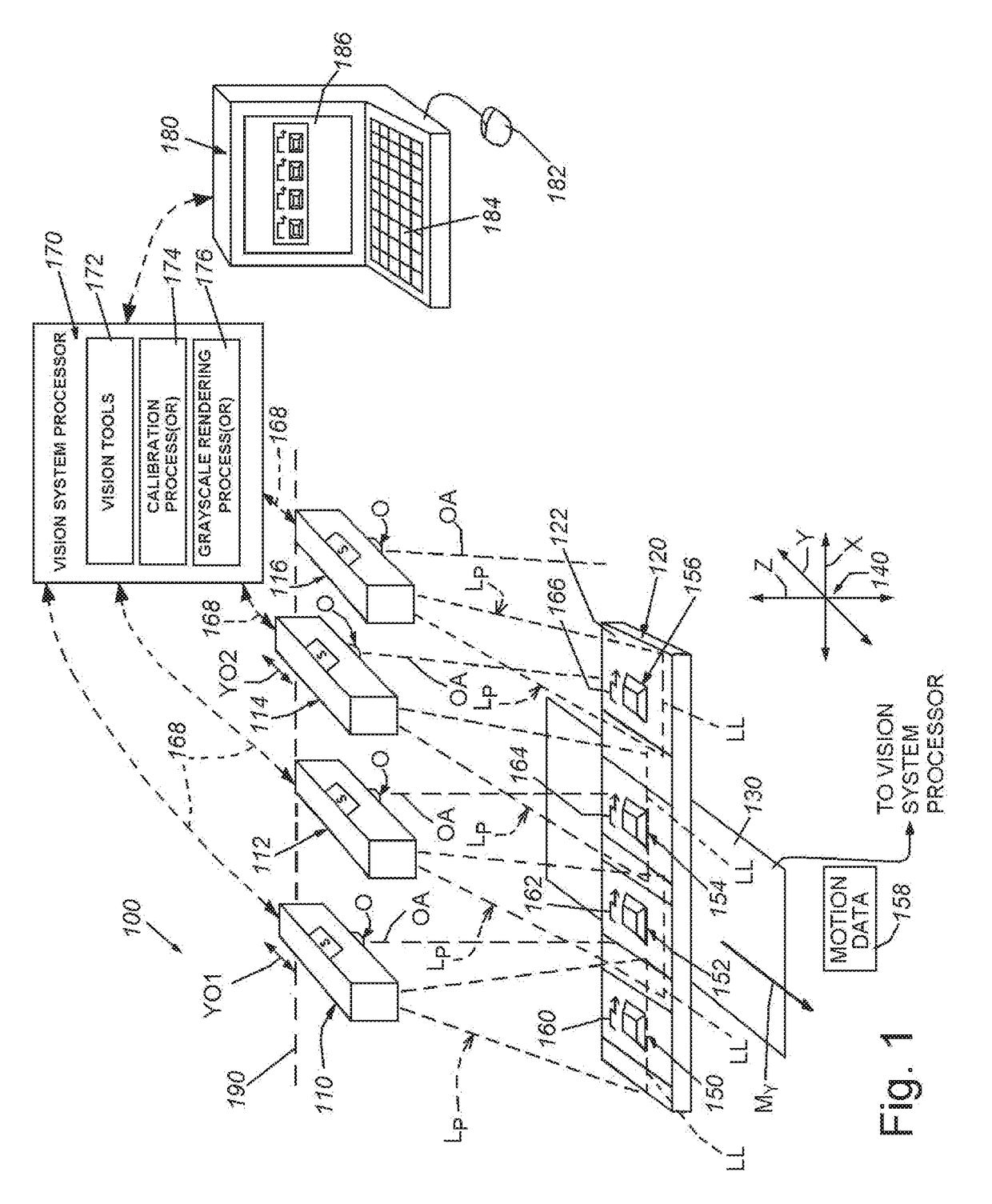
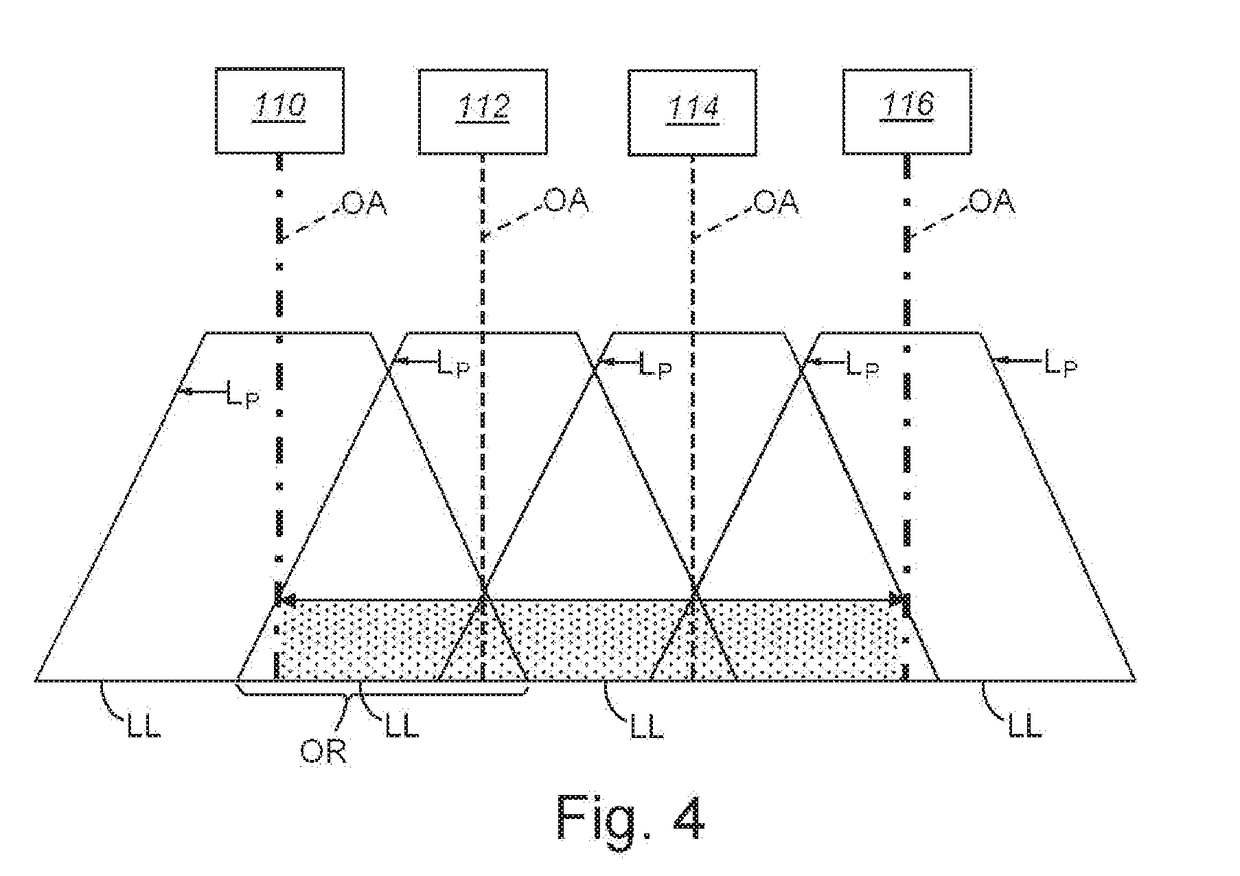
[0052]FIG. 1 details a vision system arrangement 100 that includes a plurality of (3D) displacement sensors 110, 112, 114 and 116. In this exemplary arrangement, four sensors are depicted. However at least two and greater than four sensors can be employed as the exemplary “plurality” as defined herein. The sensors 110, 112, 114, 116 can be arranged in a variety of orientations that are typically side-by-side with respect to each other as shown to define a widened (in the x-axis direction as defined below) field of view (FOV). The 3D sensors 110, 112, 114 and 116 in this exemplary arrangement are implemented as so-called laser profilers or laser displacement sensors that rely upon relative motion (arrow My) generated by a motion conveyance that acts along the y-axis direction between the sensor and the object 120 under inspection to provide a range image (also termed herein a “3D image”) of the object 120. As shown, in this embodiment, motion My is generated b...


PUM


Abstract

This invention provides an easy-to-manufacture, easy-to-analyze calibration object which combines measurable and repeatable, but not necessarily accurate, 3D features—such as a two-sided calibration object/target in (e.g.) the form of a frustum, with a pair of accurate and measurable features, more particularly parallel faces separated by a precise specified thickness, so as to provide for simple field calibration of opposite-facing DS sensors. Illustratively, a composite calibration object can be constructed, which includes the two-sided frustum that has been sandblasted and anodized (to provide measurable, repeatable features), with a flange whose above/below parallel surfaces have been ground to a precise specified thickness. The 3D corner positions of the two-sided frustum are used to calibrate the two sensors in X and Y, but cannot establish absolute Z without accurate information about the thickness of the two-sided frustum; the flange provides the absolute Z information.

Description

RELATED APPLICATIONS[0001]This application is a continuation-in-part of co-pending U.S. patent application Ser. No. 14 / 936,616, entitled SYSTEM AND METHOD FOR CALIBRATING A PLURALITY OF 3D SENSORS WITH RESPECT TO A MOTION CONVEYANCE, filed Nov. 9, 2015, the teachings of which are expressly incorporated herein by reference.FIELD OF THE INVENTION[0002]This application relates to machine vision systems and more particularly to systems and methods for calibrating vision systems having multiple camera assemblies oriented to image a scene from different points of view using a calibration object or “target”.BACKGROUND OF THE INVENTION[0003]In manufacturing and assembly processes, it is often desirable to analyze an object surface to determine the nature of features and / or irregularities. The displacement (or “profile”) of the object surface can be determined using a machine vision system (also termed herein “vision system”) in the form of a laser displacement sensor (also termed a laser be...

Claims


Application Information

Patent Timeline
Patent Type & Authority Applications(United States)
IPC IPC(8): G06T7/80H04N13/02H04N17/00
CPCH04N13/246H04N17/002G06T7/85G01B11/245G01B11/2504H04N23/90
Inventor WALLACK, AARON S.WOLFF, ROBERT A.MICHAEL, DAVID J.WANG, RUIBINGZHU, HONGWEI
Owner COGNEX CORP
Why Eureka
Try Eureka