Decorative layer-attached transparent plate and display device

Active Publication Date: 2019-01-03
ASAHI GLASS CO LTD
View PDF2 Cites 5 Cited by
  • Summary
  • Abstract
  • Description
  • Claims
  • Application Information

AI Technical Summary

Benefits of technology

[0129]Since either or both of the protrusions 57 and the recesses 59 are provided at the end portion 43 of the decorative layer 3 provided on the transparent plate 2, a boundary between the decorative layer 3 and the transparent plate 2 looks blurred in human eye.
[0130]Therefore, the color difference at the boundary between the transparent plate 2 and the decorative layer 3 is reduced and becomes inconspicuous, as compared with a case where the transmittance is constant.
[0131]The full width at half maximum W1 of the protrusion 57 is 20 μm or more and 200 μm or less and the height L1 is 20 μM or more and 100 μm or less, and these are dimensions which is close to, equal to, or smaller than the resolution of the human eye. Therefore, the boundary between

Problems solved by technology

However, the requirements for the color and physical properties which are required for the decorative layer cannot be completely compatible with each other in some cases.
In such a case, the physical properties are prioritized

Method used


Image

  • Decorative layer-attached transparent plate and display device
  • Decorative layer-attached transparent plate and display device
  • Decorative layer-attached transparent plate and display device

Examples


modified example

[0147]The present invention is not limited only to the above-described embodiments, and various improvements, design modifications and the like can be made within a range without departing from the gist of the present invention. Specific procedures, structures and the like when carrying out the present invention may adopt other structures or the like within a range where the object of the present invention can be achieved.

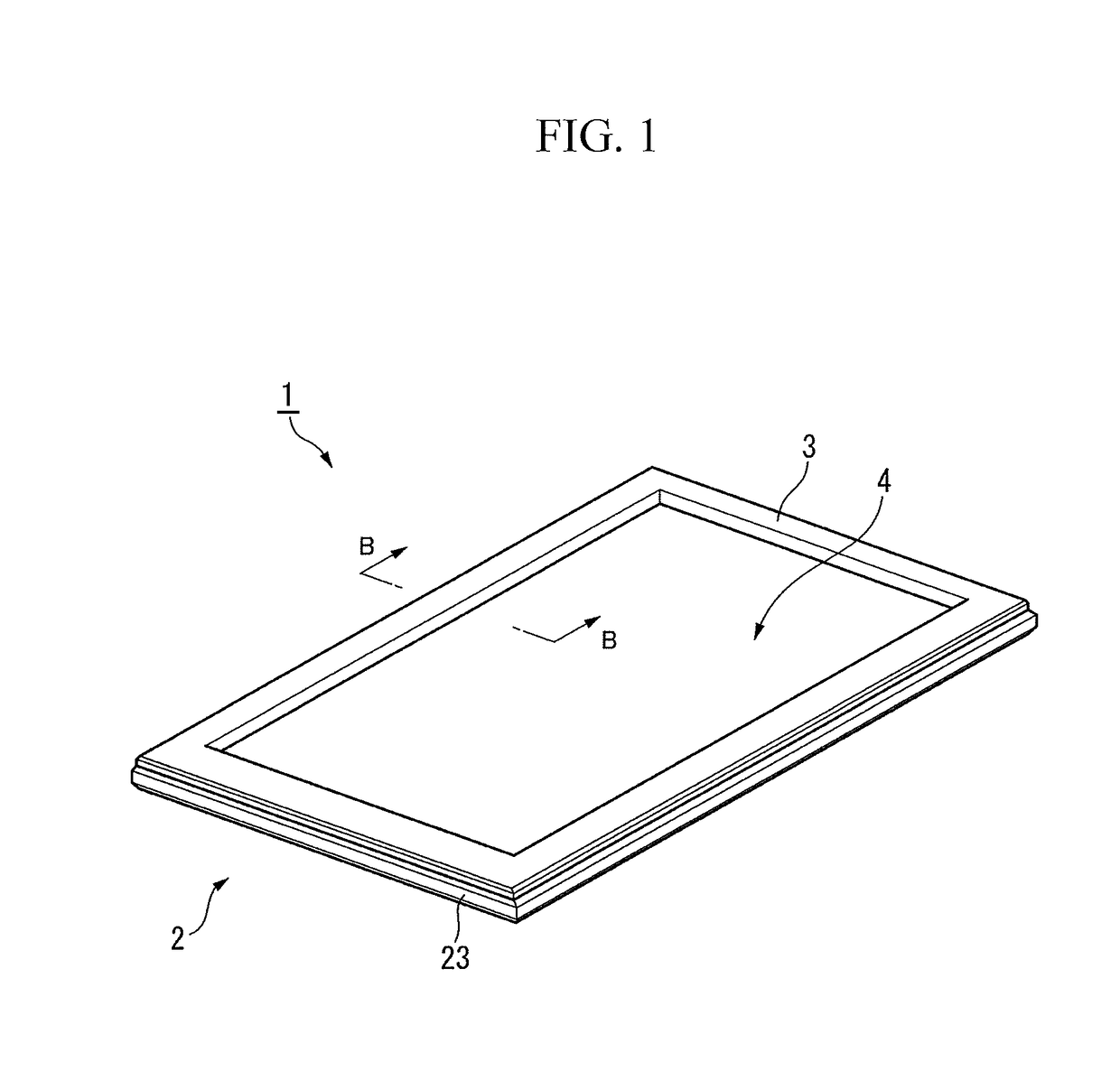
[0148]For example, as the transparent plate 2, a plate with various shapes and materials can be used according to applications.

[0149]Examples of the shape may include not only a plate having only the flat surface, but also a plate having a curved face at least on a portion and a plate having a recess. For example, in the case where the transparent plate 2 is made of glass, a bent glass may be used. In the case where a bent glass is used for the transparent plate 2, even when a counterpart member on which the decorative layer-attached transparent plate 1 is mounted ...

example 1

[0188]The glass plate was subjected to treatments of (1) an anti-glare treatment, (2) an end face grinding treatment, (3) a chemical strengthening treatment and an alkali treatment, and (4) a decorative layer formation, in the order. Specific treatments are as follows.

(1) Anti-Glare Treatment

[0189]The second main surface 22 of the glass plate was subjected to an anti-glare treatment by a frost treatment in the following procedure.

[0190]First, an acid-resistant protective film (hereinafter simply referred to as “protective film”) was bonded to a main surface (first main surface 21) of the glass plate on a side not subjected to the anti-glare treatment. The resultant glass plate was immersed in an aqueous solution of 3% by mass of hydrogen fluoride for 3 minutes. Then, the glass plate was etched to remove contaminants adhered to the second main surface 22 of the glass plate. Subsequently, the glass plate was immersed in a mixed aqueous solution of 15% by mass of hydrogen fluoride and ...

example 2

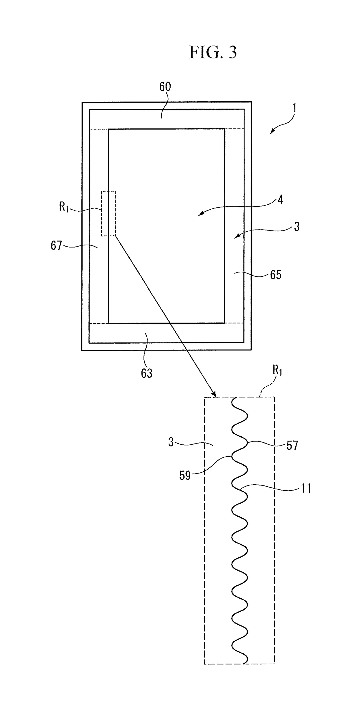
[0201]As illustrated in FIG. 8, only a recess 59 was formed in the vicinity of the inner peripheral corner portion (right upper end portion of the right side decorative layer 65) of the frame in the same manner as in Example 1, except that in (4) decorative layer formation, similarly to Example 1, the printing conditions at a portion forming the waveform was changed such that the printing pitch was narrowed to 50% to 70% and the discharge amount of the ink was also reduced to 30% to 50% in terms of the volume ratio as compared with the other portion not forming a waveform.

[0202]The enlarged view of the inner peripheral corner portion was shown in FIG. 12. In the vicinity of the inner peripheral corner portion of the decorative layer 3, only the recess 59 was formed, the depth L2 was 39 μm, and the full width at half maximum W2 was approximately 100 to 120 μm. From the results, it was found that the recess 59 can be formed by using the ink jet device. The vicinity of the waveform for...


PUM

PropertyMeasurementUnit
Lengthaaaaaaaaaa
Lengthaaaaaaaaaa
Lengthaaaaaaaaaa

Abstract

The present invention relates to a decorative layer-attached transparent plate including: a transparent plate which is formed of a visible light-transmitting material and has two main surfaces; and a decorative layer provided on one of the main surfaces, in which the decorative layer has at least one of a protrusion and a recess at an end portion thereof, in plan view as viewed from the one of the main surfaces.

Description

TECHNICAL FIELD[0001]The present invention relates to a decorative layer-attached transparent plate and a display device.BACKGROUND ART[0002]A car navigation system, on-vehicle information equipment such as audio, and portable communication equipment include a display device.[0003]The display device is provided with a protective cover, which is a sheet-like transparent plate, on a front face of a display panel via an adhesive layer (Patent Document 1). The protective cover has functions of reducing external light reflection, protecting the display panel from external shock, and the like. For example, a light-shielding decorative layer with a frame shape is provided on a surface of the protective cover on a display panel side. The decorative layer has functions of concealing wiring on the display panel side, preventing illumination light from leaking from the periphery of the display panel by concealing the illumination light of backlight, and the like in addition to the function of ...

Claims


Application Information

Patent Timeline
IPC IPC(8): B32B27/08G02F1/1335B32B27/30G02F1/1333B32B27/36B32B27/38
CPCB32B27/08G02F1/133502B32B27/308B32B27/306G02F1/133308B32B27/365B32B27/38G02F2001/133331B32B2307/4023B32B2307/412B32B2457/202B60K37/00B60R11/02B60R11/0258G02F1/133512B32B2307/732B32B27/16B32B2307/536B32B2457/206B32B7/12B32B2255/20B32B2307/75B32B3/30B32B2307/71B32B2255/10B32B2457/208B32B2307/584B32B2605/006B32B27/06B32B2307/418B32B3/08B32B2255/26B32B2307/4026B32B17/06G02F1/133331
Inventor ITO, JUNTAKAI, AZUSA
Owner ASAHI GLASS CO LTD
Why Eureka
Try Eureka