Methods and systems of anchoring an unmanned aerial vehicle on a ground station

a technology of unmanned aerial vehicles and ground stations, applied in the direction of control without feedback, landing aids, transportation and packaging, etc., can solve the problems of considerable expense, the possibility of damaging or destroying a uav, and the addition of time and expens

Active Publication Date: 2019-01-03
PERCEPTO ROBOTICS LTD
View PDF0 Cites 27 Cited by
  • Summary
  • Abstract
  • Description
  • Claims
  • Application Information

AI Technical Summary

Benefits of technology

[0013]Optionally, the landing surface is covered with an anti-glare coating to prevent light reflections from the landing surface.

Problems solved by technology

However, typically, UAVs are remote controlled, thus necessitating an operator to control the movements of the UAV and its landing process.
This becomes problematic, however, when the UAV is deployed over obscured areas of land and / or requires intensive, long-range remote control scenarios that often include the need to remotely land a UAV (e.g., in order to recharge or replace a battery).
The remote landing process for an operator, however, is often difficult, error-prone and task-dependent, which increases the probability of damaging or destroying a UAV, resulting in considerable expense.
In addition, a damaged UAV may delay a project, causing additional time and expense.
Frequently, however, an operator requires extensive training and practice to be able to successfully remotely land a UAV on a consistent basis.
The time and expense required to train an operator to perform remote UAV landings is cost prohibitive to many companies that would benefit from the use of a UAV.
Moreover, even when adequately trained, an operator still has a fairly high risk of damaging or destroying a UAV during a remote UAV landing.

Method used


Image

  • Methods and systems of anchoring an unmanned aerial vehicle on a ground station
  • Methods and systems of anchoring an unmanned aerial vehicle on a ground station
  • Methods and systems of anchoring an unmanned aerial vehicle on a ground station

Examples


Embodiment Construction

[0036]The present invention, in some embodiments thereof, relates to an unmanned aerial vehicle (UAV) ground station and, more particularly, but not exclusively, to anchoring a UAV to a ground station when landed.

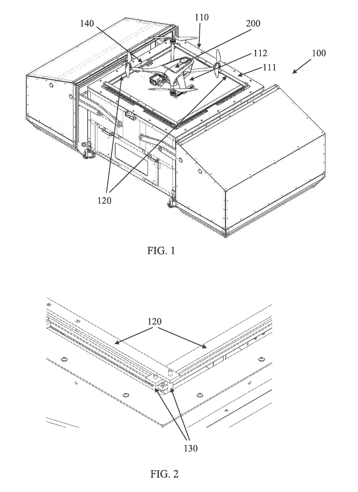
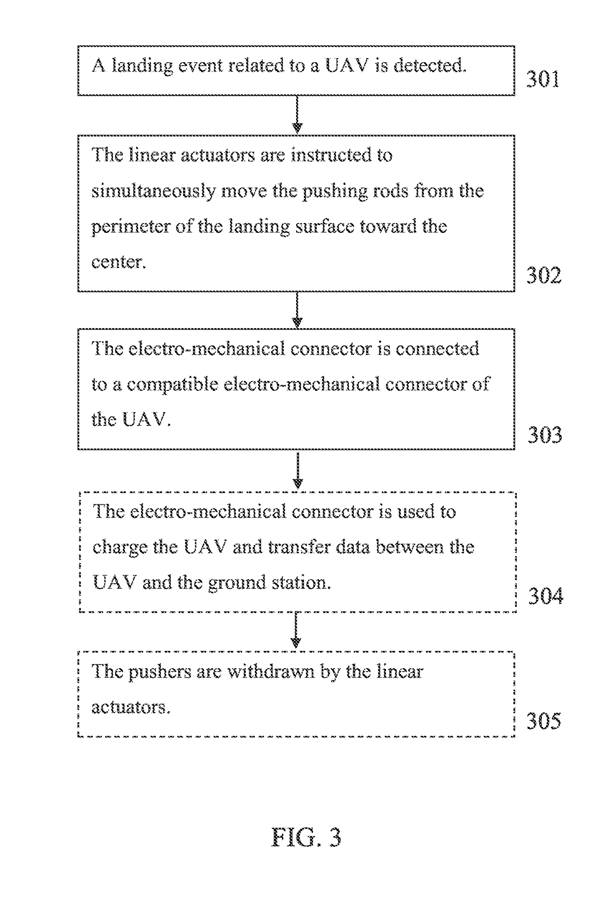
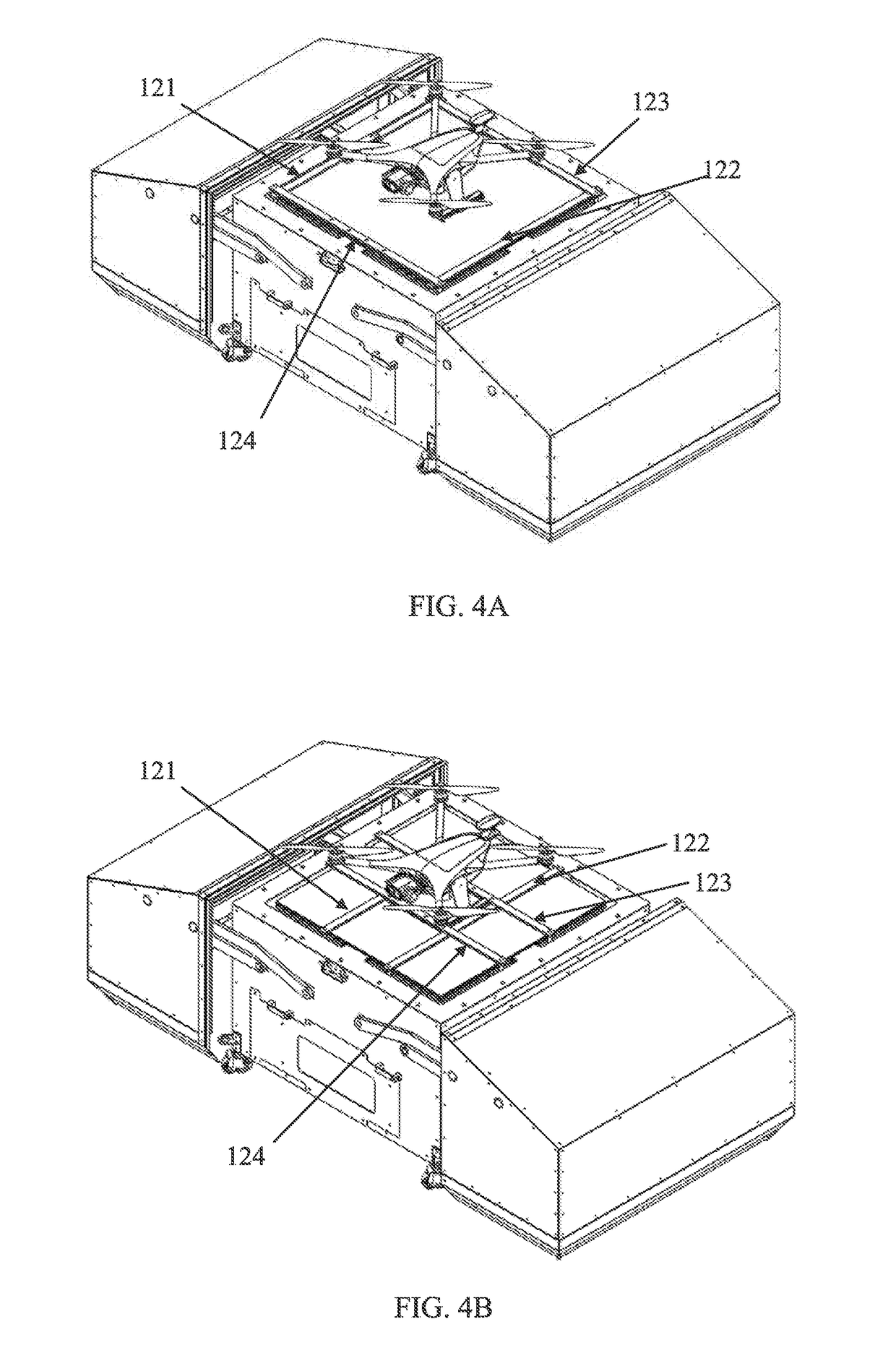
[0037]According to some embodiments of the present invention, there is provided a ground station for a UAV which includes a landing surface and pushers (for example horizontal pushing rods) that anchors the UAV when landed. When a landing event is detected by a landing detection controller, it instructs linear actuators to move the pushers simultaneously from the perimeter of the landing surface toward the center of the landing surface. The UAV is then held by the pushers at the center of the landing surface.

[0038]At least one electro-mechanical connector is attached to one of the pushers, and is connected to a compatible electro-mechanical connector of the UAV when the UAV is held by the pushers. The electro-mechanical connectors may include compatible sets of teeth to fac...


PUM


Abstract

An unmanned aerial vehicle (UAV) ground station, comprising: a landing surface having a perimeter and a center; a plurality of pushers held above the landing surface by a plurality of linear actuators; at least one electro-mechanical connector attached to one of the plurality of pushers, mechanically adapted to be electrically connected to a compatible electro-mechanical connector of a UAV; and a landing detection controller adapted to instruct the plurality of linear actuators to move the plurality of pushers simultaneously from the perimeter toward the center when a landing event related to the UAV is detected.

Description

FIELD AND BACKGROUND OF THE INVENTION[0001]The present invention, in some embodiments thereof, relates to an unmanned aerial vehicle (UAV) ground station and, more particularly, but not exclusively, to anchoring a UAV to a ground station when landed.[0002]An unmanned aerial vehicle (UAV), commonly known as a drone and referred to as a Remotely Piloted Aircraft (RPA) by the International Civil Aviation Organization (ICAO), is an aircraft without a human pilot aboard. Its flight is controlled either autonomously by onboard computers or by the remote control of a pilot on the ground or in another vehicle. The typical launch and recovery method of an unmanned aircraft is by the function of an automatic system or an external operator on the ground.[0003]Drones of commercial value are the result of recent advances in microprocessors, GPS, sensors, batteries, motors, lightweight structural materials, and advanced manufacturing techniques. Commercially utilized UAVs may efficiently perform ...

Claims


Application Information

Patent Timeline
Patent Type & Authority Applications(United States)
IPC IPC(8): B64F1/12B64F1/20B64C39/02G05D3/10
CPCB64F1/12B64F1/205B64C39/024G05D3/10B64C2201/024B64C2201/20H02J7/0042B64F1/125B64F1/007B60L53/16B60L53/36B60L2200/10Y02T10/70Y02T10/7072Y02T90/14Y02T90/12B64U80/25B64U70/97B64U80/30B64U70/99B64U10/10B64U10/13B64U80/00
Inventor RAZ, RAVIVJAFFE, JONATHANBLONDER, SAGI
Owner PERCEPTO ROBOTICS LTD
Why Eureka
Try Eureka