System, apparatus, and method for providing emergency support services

Inactive Publication Date: 2019-01-03
OPOSSUM LTD
View PDF6 Cites 3 Cited by
  • Summary
  • Abstract
  • Description
  • Claims
  • Application Information

AI Technical Summary

Benefits of technology

The present invention helps capture additional information during emergency situations by utilizing camera devices owned by public or government. A camera device can be activated when a person owns it and wishes to capture details on the emergency situation. The camera device can record image, audio, or video of the hazard situation. This technology helps improve the efficiency and coordination of rescue teams by providing precise localization, accurate assessment of the situation, and effective support to the caller while waiting for the rescue team. Overall, this invention helps save time and optimize resource utilization for medical emergencies.

Problems solved by technology

However, sometimes during an emergency, victims do not have time or ability to stay connected and clearly convey their circumstances or location to an emergency service provider.
Furthermore, in an emergency, victims generally do not have enough time for sustaining a call with the emergency service providers to explicate the emergency.
Therefore, emergency service providers oftentimes remain deprived of any additional information required for assisting the victims during emergencies.
However, victims are mostly hastened by the situation and provide very limited information.
Also, there is no way to determine if the provided emergency information is existent or misleading.
However, in such emergency situations victims are generally panic-stricken and therefore have receded abilities to correctly understand instructions provided by the emergency service providers.
Ultimately, the emergency service providers get averted from efficiently providing medical help to the victims on time and the victims gets deprived off the medical attention they deserve.

Method used


Image

  • System, apparatus, and method for providing emergency support services
  • System, apparatus, and method for providing emergency support services
  • System, apparatus, and method for providing emergency support services

Examples


Embodiment Construction

[0031]The description shall now refer in detail to the various forms of embodiment of the present invention, of which one or more examples are shown in the attached drawings. Each example is supplied by way of illustration of the invention and shall not be understood as a limitation thereof. For example, the characteristics shown or described insomuch as they are part of one form of embodiment can be adopted on, or in association with, other forms of embodiment to produce another form of embodiment. It is understood that the present invention shall include all such modifications and variants.

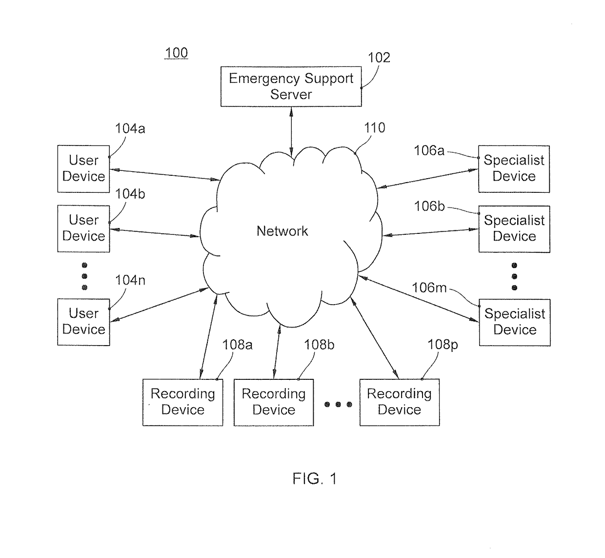
[0032]FIG. 1 illustrates an exemplary environment 100 where various embodiments of the present invention are implemented. The environment 100 includes an emergency support server 102 connected to a plurality of devices 104a-n, 106a-m, and 108a-p via a network 110, wherein the numbers n, m, and p are arbitrary numbers representing same or different number of devices. Hereinafter, the user devices...


PUM


Abstract

An emergency support system includes a first communication device used by the user and a second communication device of an emergency service provider. The first communication device is configured to automatically detect a triggering event corresponding to the emergency and to transmit its current geographical location along with images / video of its surroundings to the second communication device. The second communication device is configured to automatically or manually analyze the received information transmitted by the first communication device to determine at least one suitable tutorial for displaying at the first communication device. The second communication device is further configured to automatically activate other camera devices or surveillance cameras in proximity to the first communication device for capturing additional details corresponding to the reported emergency to determine severity or reliability of the reported emergency. Furthermore, the emergency support system allocates in the best manner the resources in case of an emergency.

Description

FIELD OF THE INVENTION[0001]Embodiments of the present invention in general, concern a system, apparatus, and method to provide emergency support services to a user of a communication device. More particularly, embodiments of the present invention concerns to a system, apparatus, and method of automatically apprising an emergency call center corresponding to an emergency condition via a network.BACKGROUND OF THE INVENTION[0002]Nowadays, wireless communication devices (e.g., tablets, cell phones, Smart phones, PDAs, or other types of portable communication devices) are omnipresent. Further, the wireless communication devices have been used to store emergency information, also known as ICE (In Case of Emergency) information. More specifically, an ICE application in a wireless communication device enables its owner to store information in case of an emergency situation (e.g. medical history like allergies, current medications, emergency contact persons, emergency service providers etc....

Claims


Application Information

Patent Timeline
IPC IPC(8): H04W4/90H04W4/029H04W4/44
CPCH04W4/90H04W4/029H04W4/44
Inventor MARCHIOL, LUCAPARLAMENTO, STEFANOPUPPIS, MATTEO
Owner OPOSSUM LTD
Why Eureka
Try Eureka