
Nozzle assembly of biological printer and biological printer

Active Publication Date: 2019-01-10
SICHUAN REVOTEK CO LTD
View PDF2 Cites 2 Cited by
  • Summary
  • Abstract
  • Description
  • Claims
  • Application Information

AI Technical Summary

Benefits of technology

The patent is about a spray head assembly for a bioprinter that allows for easy adjustment of the flow rate of the bioprinting material fluid. This is accomplished by providing a port at one end of the flow channel and designing the spray head in a structural form composed of an equal diameter portion and a reduced diameter portion. The relative positions of the reduced diameter portion and the port can be changed to adjust the circulation area of the spray head assembly and thus adjust the flow rate of the bioprinting material fluid sprayed by the spray head. The technical solution is convenient, easy to use, and favorable for implementability.

Problems solved by technology

Exactly due to the aforementioned characteristics, the 3D bioprinting technology is confronted with many specific technical problems in development.
The disadvantages of the prior art lie in that the circulation area of the existing spray head for spraying biological printing material is constant.

Method used


Image

  • Nozzle assembly of biological printer and biological printer
  • Nozzle assembly of biological printer and biological printer

Examples


first embodiment

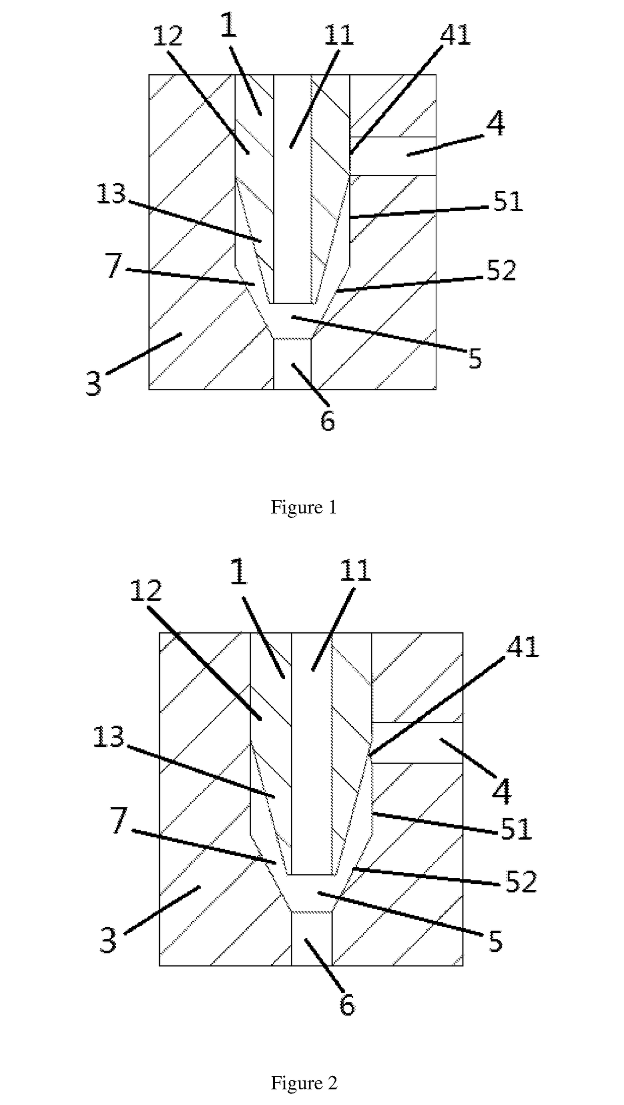
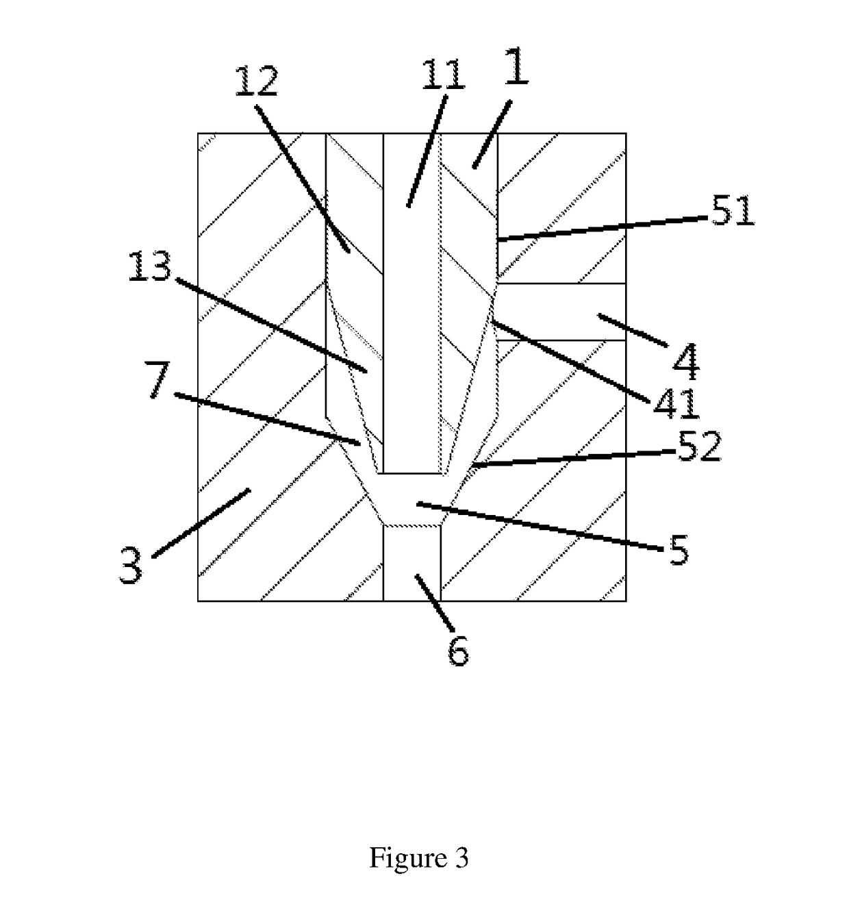
[0056]As the present disclosure, the bioprinter spray head assembly comprises a spray head groups including a plurality of alternative spray heads, wherein, each of the plurality of alternative sprayer heads are provided with corresponding equal diameter portion 12 and reduced diameter portion 13 having lengths different from the same of other alternative sprayer heads. The spray head 1 is selected from a plurality of alternative spray heads as necessary, so as to realize one of the fully occluded state, the partially occluded state and the fully open state. In other words, by replacing the spray head having an equal diameter portion 12 and a reduced diameter portion 13 of different lengths, the position relation between the reduced diameter portion 12 of the spray head and the port 41, the size of the opening between the port 41 and the reduced diameter portion 13 is further adjusted, to realize one of the fully occluded state, the partially occluded state and the fully open state,...

second embodiment

[0057]As the present disclosure, the spray head 1 is movable in the passage 5, such that the positional relation between the spray head 1 and the passage 5 varies, thereby changing the positional relation between the reduced diameter portion 13 of the spray head and the port 41. Further, the size of the opening between the port 41 and the reduced diameter portion 13 is changed, so that a shift among the fully occluded state, the partially occluded state and the fully open state may be realized, so as to effectuate that the flow rate of the second material is dynamically adjustable.

[0058]The spray head 1 may be integrally translated in the passage, and may also be partially movable. For example, the equal diameter portion 12 or the reduced diameter portion 13 of the spray head 1 is extensible. The spray head 1 is further designed into a extensible structure in the passage 5, in which the extensible length of the spray head 1 in the passage 5 varies, so as to change the positional rel...


PUM

PropertyMeasurementUnit
Diameteraaaaaaaaaa

Abstract

The present disclosure relates to a bioprinter spray head assembly, comprising a mounting block having a passage and a spray head mounted in the passage, wherein a first flow channel is provided in the mounting block, one end of the first flow channel is provided with a port communicating with the passage; the spray head comprises an equal diameter portion away from an outlet of the passage and a reduced diameter portion close to the outlet of the passage, wherein a second flow channel is formed between the reduced diameter portion and the passage, an opening is formed between the reduced diameter portion and the port to communicate the first flow channel and the second flow channel, and the equal diameter portion is configured to occlude the port. The adjustment of the circulation area of the spray head assembly may be achieved by changing the relative positions of the reduced diameter portion and the port, so that the adjustment is convenient and easy to carry out, and there is a favorable implementability.

Description

TECHNICAL FIELD[0001]The present disclosure relates to the field of bioprinting, and especially relates to a bioprinter spray head assembly and a bioprinter.BACKGROUND ART[0002]3D bioprinting refers to the printing of biological materials (including natural biological materials and synthetic biological materials or cellular solutions) into a designed three-dimensional structure through the principles and methods of 3D printing. Differing from those printed by ordinary 3D printing technology, the biological tissues or organs produced by 3D bioprinting technology have certain biological functions and need to provide conditions for the further growth of cells and tissues. Exactly due to the aforementioned characteristics, the 3D bioprinting technology is confronted with many specific technical problems in development.[0003]In the field of 3D bioprinting, the print technique of taking cells as a printing material is referred to as cell three-dimensional printing technology. People may u...

Claims


Application Information

Patent Timeline
IPC IPC(8): B29C64/209
CPCB29C64/209B33Y30/00B29C67/24B29C64/112B29C48/255B29C48/304B29C48/49B05B1/3026B05B1/3066B05B7/12
Inventor LI, YIJUNWANG, DEMINGZHANG, LEQINGWEN, XUEMIN
Owner SICHUAN REVOTEK CO LTD
Learn More