Method And Apparatus For Weighing An Elongate Object

Active Publication Date: 2019-01-10
VESTAS WIND SYST AS
View PDF8 Cites 2 Cited by
  • Summary
  • Abstract
  • Description
  • Claims
  • Application Information

AI Technical Summary

Benefits of technology

[0090]In aspects, there may be provided ancillary equipment which may facilitate automation of aspects of the method described herein. In particular, there may be provided a load gauge control module 60 in a communication network with load gauge 41, 42. The load gauge control module 60 may be associated with an input 63 and an output 62. Input data may include data for programming of the load gauge control module 60, such as geometry data for individual objects 14 of for object types, design types or designations. This may for example enable the load gauge control module 60 to automatically calculate, using measured weight values from the load gauges 41, 42, a balanced weight for an object 14 being examined. Objects 14 with barcodes or other machine-readable or recognisable markings may be automatically recognised by the load gauge control module 60. Following a pair of load measurement inputs from the load gauges 41, 42, and using geometry data for the relevant object, coupled with the relevant algorithm for finding a balanced weight, the control module 60 may output the relevant balanced weight information in any appropriate format, for use. Additionally or alternatively, an indicator module 61 may allow ready recognition of load gauge m

Problems solved by technology

The determination of the weight of a large object can be a relatively unwieldy task, due to the need to manipulate, handle and position a large object, while at the same time ensuring that the weight determination can be accurately carried out.
How

Method used


Image

  • Method And Apparatus For Weighing An Elongate Object
  • Method And Apparatus For Weighing An Elongate Object
  • Method And Apparatus For Weighing An Elongate Object

Examples


Example

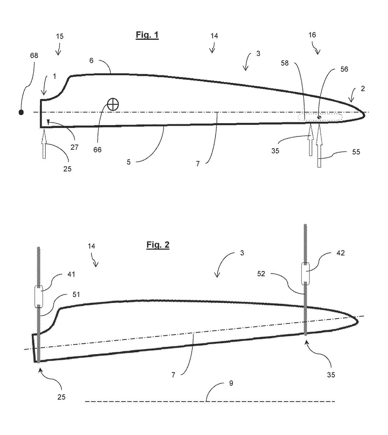
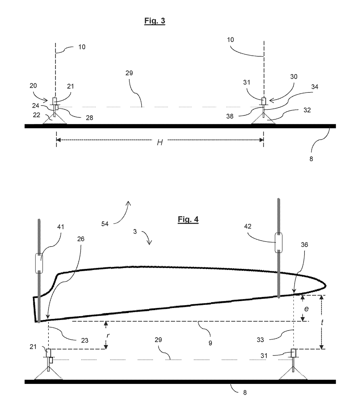
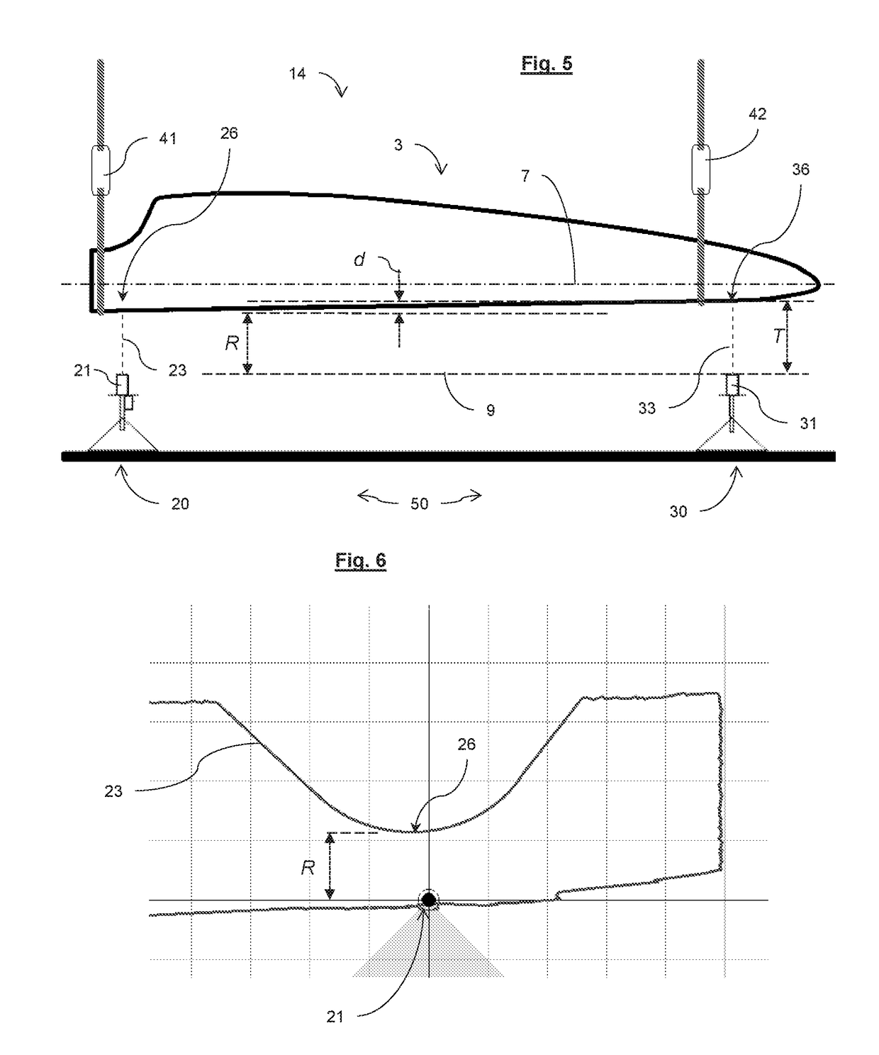
[0065]An elongate object 14 is shown in FIG. 1, extending between a tip region 16 and a root region 15, and having a centre of gravity 66. Large elongate objects 14 of any description may generally need to be examined before their release from a manufacturing facility. This examination may include making a number of measurements and carrying out tests and may frequently include weighing. In some cases, it may be useful to determine the position of the centre of gravity 66 of an object 14. Still further, in the case of large objects 14 subject to or designed to undergo some kind of rotational motion, it may be desirable to calculate a balanced weight value about a defined—i.e. intended—centre of rotation of the elongate object 14. This may allow an improved prediction of the dynamics the elongate object 14 during rotational movement. It may also allow objects to be subsequently weight-adjusted during a finishing stage, in order to exhibit consistent characteristics. The balanced weig...


PUM


Abstract

Method and apparatus for weighing an elongate object extending between a root end and a tip end thereof, said method including: providing a respective tip load measurement gauge and root load measurement gauge; and providing a suspending arrangement configured for suspending said elongate object from said tip load measurement gauge and from said root load measurement gauge; and suspending said object in a horizontal orientation; and recording a tip load and a root load from respective said load measurement gauges, said method being additionally characterised by: providing a weighing area; and fixing an inclinometer to said suspended blade and load gauge arrangement; and suspending said elongate object from said tip load gauge and from said root load gauge; and adjusting the horizontality of said elongate object in response to signals from said inclinometer prior to said step of recording said tip load and said root load. Alternatively, an inclinometer may be replaced by placing a first distance sensor at a first location on a ground surface; and placing a second distance sensor at a second location on said ground surface; and suspending said elongate object from said tip load gauge and from said root load gauge such that a said root end thereof is suspended proximate said first distance sensor and a said tip end thereof is suspended proximate said second distance sensor; and measuring a first distance between said first distance sensor and a said root portion of said elongate object and; and measuring a second distance between said second distance sensor and a said tip portion of said elongate object; and then adjusting the horizontality of said elongate object in response to said first and second distance readings prior to said step of recording said tip load and said root load.

Description

[0001]The present invention relates to improvements in weighing elongate objects. In particular, the present invention relates to weighing large, elongate objects, preferably by suspending the objects. Still more particularly, the present invention relates to weighing wind turbine components such as wind turbine blades.[0002]It may be desirable to determine a product's assembled weight, for example before releasing the product, or as part of a finishing or quality checking process. Weighing an object may be carried out in order to ascertain its centre of gravity location. The determination of the weight of a large object can be a relatively unwieldy task, due to the need to manipulate, handle and position a large object, while at the same time ensuring that the weight determination can be accurately carried out. Time can be lost. Specialised equipment can be needed. In some cases, specialised equipment may be needed for each product type or model.[0003]For example, it has been known...

Claims


Application Information

Patent Timeline
IPC IPC(8): F03D13/35G01M1/12G01G19/18
CPCF03D13/35G01M1/122G01G19/18F05B2260/83F05B2230/10F05B2240/30F05B2260/80F05B2220/30F03D17/00G01G23/002Y02E10/72Y02P70/50B66C1/108F03D13/10
Inventor VIND, FLEMMINGIRISSAPPANE, VIJAYASANKAR
Owner VESTAS WIND SYST AS
Why Eureka
Try Eureka