Endpointing for focused ion beam processing

Active Publication Date: 2016-05-05
FEI COMPANY
View PDF15 Cites 10 Cited by
  • Summary
  • Abstract
  • Description
  • Claims
  • Application Information

AI Technical Summary

Benefits of technology

[0006]An object of the invention is to facilitate aut

Problems solved by technology

As nanotechnology produces smaller and smaller circuits and other elements, it becomes more difficult to produce and manipulate the nanometer scale objects.
While it is known that it is desirable to automate nano-processes, the precise nature of those processes makes automation difficult, if not impossible for many processes.
Scanning electron microscopes (SEM) are used to observe microscopic features, but as the feature size of fabricated structures decreases, the resolut

Method used


Image

  • Endpointing for focused ion beam processing
  • Endpointing for focused ion beam processing
  • Endpointing for focused ion beam processing

Examples


Example

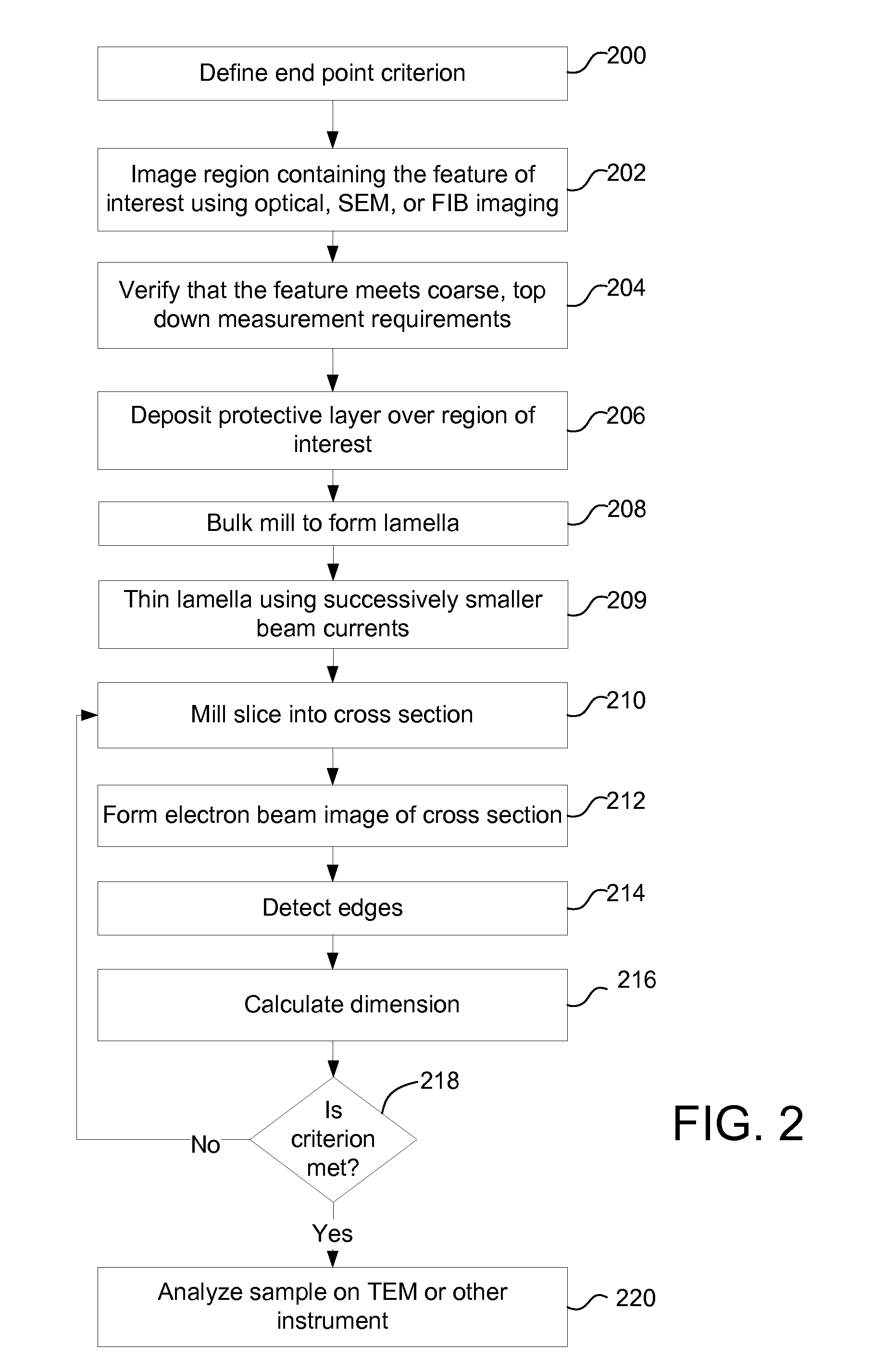
[0017]In accordance with a preferred embodiment of the invention, a system determines when to stop milling by determining whether a criteria is met, the criteria being based on a measurement from an edge determined by edge recognition software.

[0018]Applicants have found that in some applications, conventional image recognition software is inadequate for endpointing of FIB milling Conventional image recognition scores a current image relative to a stored reference image with regard to two primary conditions: image uniqueness and contrast. The best scoring reference image is chosen as the “recognized” image, and acted upon.

[0019]A preferred embodiment uses image recognition software for gross determination of the endpoint, and then uses a dimension determined using edge recognition for fine endpointing. Edge recognition is simpler than image recognition and looks at the contrast of the pixels in an image and determines an edge by a change in contrast. A smoothing function is typicall...


PUM


Abstract

To expose a desired feature, focused ion beam milling of thin slices from a cross section alternate with forming a scanning electron image of each newly exposed cross section. Milling is stopped when automatic analysis of an electron beam image of the newly exposed cross section shows that a pre-determined criterion is met.

Description

TECHNICAL FIELD OF THE INVENTION[0001]The present invention relates to charged particle processing and in particular to a technique for automating a charged particle beam process.BACKGROUND OF THE INVENTION[0002]As nanotechnology produces smaller and smaller circuits and other elements, it becomes more difficult to produce and manipulate the nanometer scale objects. While it is known that it is desirable to automate nano-processes, the precise nature of those processes makes automation difficult, if not impossible for many processes.[0003]The line widths of features achievable in semiconductor processing are significantly less than 100 nm. To control critical processes during fabrication, it is necessary to observe and measure the results of those processes. Scanning electron microscopes (SEM) are used to observe microscopic features, but as the feature size of fabricated structures decreases, the resolution of SEM is insufficient, and it is necessary to observe defects on a transmi...

Claims


Application Information

Patent Timeline
IPC IPC(8): H01J37/317H01J37/28H01J37/22H01J37/30
CPCH01J37/317H01J37/3005H01J37/28H01J2237/08H01J2237/31749H01J2237/2814H01J37/22H01J37/304H01J37/3056H01J2237/24578H01J2237/31745H01J2237/30466
Inventor FULLER, SCOTT EDWARDDONALD, JASONSEEMUNTCHAIBOWORN, TERMSUPT
Owner FEI COMPANY
Why Eureka
Try Eureka